Book Categories:



















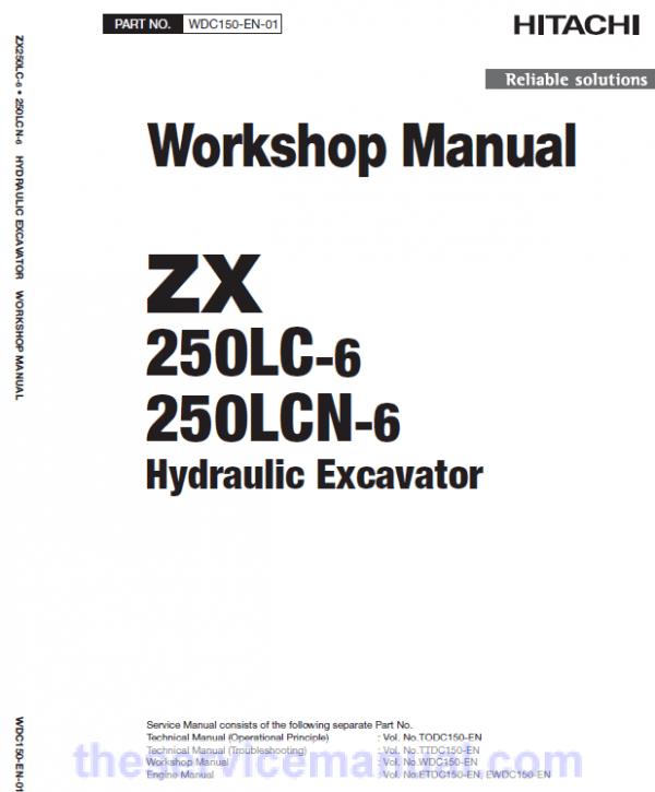

Hitachi ZX250LC-6 and ZX250LCN-6 ZAXIS Excavator Repair Manual
$49.00
Hitachi ZX250LC-6 and ZX250LCN-6 ZAXIS Excavator Repair Manual
The manual is applicable for the Hitachi Excavator Model ZX250LC-6 and ZX250LCN-6
Format: PDF
Language: English
Service Repair Manual consists of the following:
Service Repair Manual (Troubleshooting) : Vol. No.TODC150-EN
Service Repair Manual (Operation) : Vol. No.TTDC150-EN
Workshop Manual : Vol. No.WDC150-EN
Hitachi ZX250LC-6 and ZX250LCN-6 ZAXIS Excavator Repair Manual
The manual is applicable for the Hitachi Excavator Model ZX250LC-6 and ZX250LCN-6
Format: PDF
Language: English
Service Manual consists of the following:
For Model ZAXIS ZX250LC-6 and ZX250LCN-6 as mentioned above:
Service Manual (Troubleshooting) : Vol. No.TODC150-EN
Service Manual (Operation) : Vol. No.TTDC150-EN
Workshop Manual : Vol. No.WDC150-EN
Circuit Diagram
SI Units (International System of Units) is use in the manual.
Manual guide composition
Hitachi ZAXIS ZX250LC-6 and ZX250LCN-6 service manual consists of the Operating, Troubleshooting and the Workshop Manual.
- Information included in the Service Manual: Technical information needed for redelivery and delivery, operation and activation of all devices and systems, operational performance tests, and troubleshooting procedures.
- Information included in the Workshop Manual: Technical information needed for maintenance and repair of the machine, tools and devices needed for maintenance and repair, maintenance standards, and removal / installation and assemble / disassemble procedures.
To avoid injury and damage refer to the service manual and be sure to use appropriate lifting techniques and equipment when lifting heavy parts.
A ZAXIS hallmark industry-leading hydraulic technologies, and performance no other can beat. New ZAXIS provides reliable solutions: impressive fuel economy, swift front movements, and easy operation. You’ll also find Hitachi technological prowess and expertise, such as the optimize hydraulic system and engine.New ZAXIS features the key benefits of high quality, low fuel consumption, and high durability, all of which serve to ensure low running costs.New ZAXIS, which is empower by comprehensive evolution, will realize customers visions and dreams, and pioneer your colorful future
Relief Valve Manual Instructions Extract:
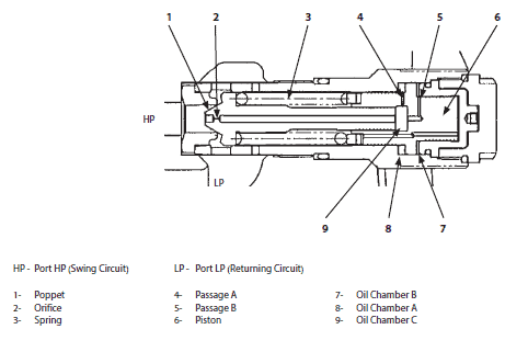
When starting or stopping swing operation, the swing circuit pressure becomes high. The relief valve prevents the circuit pressure from rising higher than the set pressure.
Low-Pressure Relief Operation (Shockless Function): 1. Pressure at port HP (swing circuit) is routed to oil chamber C (9) through orifice (2) in poppet (1).
2. Pressure oil in chamber C (9) flows to oil chamber A (8) through passage A (4) and flows to oil chamber B (7) through passage B (5).
3. As the pressure receiving area in oil chamber B (7) is larger than the pressure receiving area in oil chamber A (8), piston (6) moves to the left.
4. As long as piston (6) keeps moving, a pressure difference is developed between the front and rear of orifice (2) due to orifice (2). When this pressure difference is increased beyond the spring (3) force, poppet (1) is opened and pressure oil flows to port LP.
5. When piston (6) reaches the stroke end, the pressure difference between the front and rear of orifice (2) disappears and poppet (1) is closed.
High-Pressure Relief Operation (Overload Prevention):
1. After piston (6) reaches the stroke end, the circuit pressure becomes the normal relief set pressure.
2. When pressure at port HP increases further and is beyond the spring (3) set pressure, poppet (1) is opened and pressure oil flows to port LP.
3. When pressure at port HP is decreased to the specified level, poppet (1) is closed by the spring (3) force.
Hitachi ZX250LC-6 and ZX250LCN-6 ZAXIS Excavator Repair Manual