Description
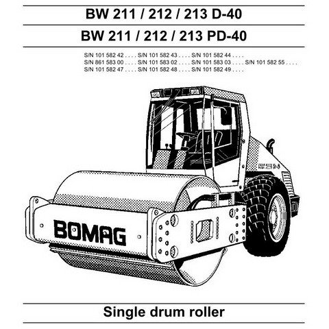
Bomag BW 211 212 213 PD-40 Service Repair Manual
Bomag BW 211 212 213 D-40 Service Repair Manual instructions describe the removal or dismantling and assembly of components and assembly
groups.
The repair of disassembled assembly groups is described as far as this makes sense with respect to available tools and spare parts supply and as far as it can be understood by a skilled mechanic and MAINTENANCE Manual
BW 211 212 213 D-40 and BW 211 / 212 / 213 PD-40
S/N 101 582 42
S/N 101 582 43
S/N 101 582 44
S/N 861 583 00
S/N 101 583 02
S/N 101 583 03
S/N 101 582 55
S/N 101 582 47
S/N 101 582 48
S/N 101 582 49
Single drum roller
Introduction:
This Bomag BW 211 212 213 PD-40 Service Repair Manual addresses the professionally qualified personnel or the after-sales service of BOMAG, and
should be of help and assistance in the correct and efficient repair and maintenance work.
This manual describes the disassembly, dismantling, assembly, installation, and repair of components and assemblies. The repair of components and assemblies is only described as this makes sense under due consideration of working means and spare parts supply.
Bomag BW 211 212 213 PD-40 Service Manual
General:
- Before changing any expensive components, such as control units, you should run a systematic troubleshooting session to eliminate any other possible fault sources. Knowledge in basic electrics is required for this purpose. If a fault was diagnosed without having pulled the plug of the control unit or inspected the wiring, this should be done before changing any parts.
- Check for good cable and ground contacts, therefore keep all mechanical transition points between
electric conductors (terminals, plugs) free of oxide and dirt, as far as this is possible. - Always use the machine-related wiring diagram for testing. If one or more faults were detected, these
should be corrected immediately. - Do not disconnect or connect the battery or generator while the engine is running.
Do not operate the main battery switch under load. Do not use jump leads after the battery has been removed.
Sensors and electric actuators on control units must never be connected individually or between external power sources for the purpose of testing, but only in connection with the control unit in question.
It is not permitted to pull plugs off while the voltage supply is switched on (terminal 15 “ON”)! Switch the voltage supply “OFF” first and pull out the plug.
Even with an existing polarity reversal protection, incorrect polarity must be strictly avoided. Incorrect polarity can cause damage to control units!
This manual contains SPECIFICATION data and OPERATION, MAINTENANCE, and REPAIR methods for the model Compactor See Section SPECIFICATIONS, of this manual, for details on significant frameworks utilized on the machine
BW 211 212 213 PD-40 Service Manual


