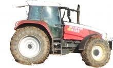
Description
Cnh Case Steyr 9000-Series Tractors Factory Service Manual
CONTROL CIRCUIT TO THE MAIN CLUTCH FOR SHUTTLE OPERATION as well as starting with and without
the clutch pedal
General information
The software has 4 reversing characteristic curves for starting or reversing without the clutch pedal. Their pressure level depends on the gear selected in the 6-speed synchronized transmission (pressure level increases when a higher gear is selected), whereby the characteristic curves for the 1st and 2nd gear are almost identical. There is only one characteristic curve for the 5th and 6th gear.
If certain rotational speed signals fail, the A68 activates the proportional valve (Y3) according to a “default characteristic curve” whose pressure curve corresponds to the characteristic curve for the 5th and 6th gear. Cnh Case Steyr 9000-Series

· If the clutch pedal is used to start, then activation of the proportional valve (Y3), and thus the main clutch, is not effected in
accordance with a characteristic curve but according to the current position of the clutch pedal.
Signal characteristic when “engaging the clutch without using the clutch pedal”
· The driver’s command to start or reverse is carried out by operating keys. This sends.
Cnh Case Steyr 9000-Series Tractors Factory Service Manual
“high” digital signals (+12 VDC) to the E-box (A68).
· A68 immediately activates a variable direct current with the characteristic of a selected characteristic curve in the range of
400 to 1060 mA for control valve Y3.
The infinite variation of the control current is effected by pulse-width modulation.
· At the same time Y3 activates a variable hydraulic control pressure of 2 to 18 bar to close the main clutch.
The increase in the control pressure is effected proportionally to the current rise – see characteristic curves on page 26.
Signal characteristic when “engaging the clutch using the clutch pedal”.
· The angular sensor (B17) for the clutch pedal supplies a variable direct voltage (VDC) of 1 to 4 volts (the signal voltage increases when the clutch pedal is fully depressed).
· The signal voltage of B17 is transmitted to the E-box (A68).
· A68 activates the control current for Y3 according to the signal voltage of B17.
· Y3 activates the hydraulic control pressure for the main clutch.
· The signal voltage of sensor B17 and the control current for Y3 bear a ratio to each other – refer to page 27.
On reaching a pedal travel of 75%, the plunger-operated switch (S46) interrupts the “high“ signal (+12 VDC) to A68. 2 clutches are
then actuated in the power-shift transmission and there is a power transfer from the engine to the main clutch.
· The power-shift transmission is actuated the moment the main clutch starts to close.
Attention: If it is discovered that the values of the control voltage and control current do not match when taking a comparison
measurement whilst troubleshooting, then it must also be checked whether the programming and code input has been carried in
accordance with the tractor type and final speed.

Reviews
There are no reviews yet.