Description
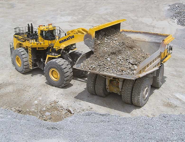
Komatsu WA1200-6 Service Shop Manual
Table of Contents:
Index and foreword
Table of contents
Table of contents
Foreword and general information
Safety notice
How to read the shop manual
Explanation of terms for maintenance standard
Handling of hydraulic components
Method of disconnecting and connecting push-pull type coupler
Handling of electric equipment
How to read electric wire code
Precautions when performing work
Standard tightening torque table
List of abbreviation
Conversion table
Specification
Specification
Specification dimension drawing
Specifications
Weight table
Table of fuel, coolant and lubricants
Structure and function
Engine and cooling system
Damper
Cooling system
Cooling fan motor
Power train
Power train
Hydraulic piping drawing of torque converter and transmission
Torque converter
Main relief valve and torque converter relief valve
Torque converter regulator valve
ECMV
Transmission
Transmission control valve
Transmission lubricating oil relief valve
Transfer
Torque converter oil cooler
Center support
Axle
Final drive
Steering system
Steering equipment layout drawing
AJSS
Steering pump
Switch pump
Steering demand valve
Rotary valve
EPC valve (for steering)
Komatsu WA1200-6 Service Shop Manual
Table of Contents:
WA
Diverter valve
The emergency steering relief valve
Steering lock valve
Brake system
Brake equipment layout drawing
Brake valve
Charge valve
Accumulator (for brake)
Slack adjuster
Brake
Parking brake
Parking brake solenoid valve
Emergency parking brake release valve
Check valve of the parking brake circuit
Undercarriage and frame
Axle mount
Center hinge pin
Jackup point
Hydraulic system
Hydraulic piping layout drawing
Work equipment control lever linkage
Hydraulic tank
Work equipment pump No
Work equipment pump No
EPC valve (for work equipment)
Neutral cutoff solenoid valve (NC valve)
Relief valve
Accumulator (for EPC valve)
Work equipment control valve
Work equipment
Work equipment linkage
Electrical system
Machine monitor system
Multifunction monitor
Work equipment and AJSS control system
Work equipment control lever
Transmission control system
Engine starting circuit
Engine stopping circuit
Electric parking brake control
Sensor
Standard value table
Standard value table
Standard value table for engine
Standard value table for chassis
Testing and adjusting
Tool for testing, adjusting, and troubleshooting
Tools for testing, adjusting, and troubleshooting
Safety precautions to follow before starting work
Engine and cooling system
Testing engine speed
Testing exhaust gas color
Table of Contents
WA
Testing and adjusting work equipment pump TVC valve oil pressure
Operation test of work equipment valve by work equipment speed (speed of work
equipment is low)
Testing hydraulic oil cooler performance
Bleeding air from the hydraulic circuit
Releasing remaining pressure in the hydraulic circuit
Work equipment
Checking center hinge pin lubrication
Adjustment method of auto grease injector delivery
Setting method of auto grease timer
Electrical system
Testing and adjusting bucket proximity switch
Adjusting lift arm potentiometer
Adjusting lift arm levelness detecting switch
Initial setting procedure for remote boom positioner (origin input method)
Checking proximity switch operation pilot lamp
Adjusting the AJSS lever angle sensor and frame angle sensor
Testing and adjusting potentiometer mounting position
Procedure for testing diodes
Basic precautions for KOMTRAX Plus controller
Inspection and maintenance of KOMTRAX Plus controller
Initial setting procedure for the KOMTRAX Plus controller
Precautions for replacing KOMTRAX Plus controller
Measurement procedure by downloading data in KOMTRAX Plus controller
Measurement procedure by multi-monitor
Special functions of multi-monitor
Pm Clinic
Outline of the measurement procedure for Pm Clinic
Preparation for measurement for Pm Clinic
Pm clinic service
Troubleshooting
General information on troubleshooting
Symptom and troubleshooting numbers
The sequence of events in troubleshooting
Check before troubleshooting
Classification and procedures of troubleshooting
Breakage of hydraulic cylinder
Failure codes table
Symptom and troubleshooting numbers
Information in troubleshooting table
Troubleshooting method for open circuit in the wiring harness of the pressure sensor system
Layout drawing of connector pins
Connector list and layout
T branch box and T branch adapter table
Table of fuse locations
Troubleshooting by failure code
Failure code [L] Double Engagement of Transmission Clutches
Failure code [N] T/M overrun
Failure code [BNX] T/M Oil Filter Clogged
Failure code [SAL] ECMV (F) Fill Switch Short Circuit
Failure code [SALH] ECMV (F) Fill Switch circuit Disconnect
Failure code [SBL] ECMV (R) Fill Switch Short Circuit
Failure code [SBLH] ECMV (R) Fill Switch circuit Disconnect
Komatsu WA1200-6 Service Shop Manual


