Description
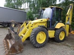
Komatsu WB97R-5, WB97S-5, WB97S-2 Backhoe-Loader Workshop Repair & Service Manual
Complete manufacturing facility shop guidebook consisting of electric wiring layouts for Komatsu WB97R-5, WB97S-5, WB97S-2 Backhoe-Loader. It coincides service guidebook utilized by dealers that guaranteed to be fully practical and also undamaged with no missing web page to save your priceless time.
This Komatsu repair handbook (including upkeep, overhaul, dismantling & setting up, change, tune-up, operation, evaluating, analysis & troubleshooting …) is split right into different sections. Each section covers a specific component or system with detailed images. A tabulation is put at the beginning of each area. Pages are conveniently found by classification, as well as each page is expandable for wonderful detail. The printer-ready PDF papers function like an appeal on all type of gadgets.
Komatsu WB97R-5, WB97S-5, WB97S-2 Workshop Repair Service Manual
” Shop Handbook (WEBM006300). pdf”.
616 web pages: Komatsu WB97R-5 Backhoe-Loader Store Guidebook.
SERIAL NUMBERS: F50003 and also UP.
” Shop Guidebook (WEBM007500). pdf”.
616 web pages: Komatsu WB97S-5 Backhoe-Loader Shop Guidebook.
IDENTIFICATION NUMBERS: F00003 and UP.
” MANUALE D’OFFICINA (WHBM002403) (IT). pdf”.
526 pages, Italian: Komatsu WB97S-2 Backhoe-Loader Manuale D’Officina.
SERIAL NUMBERS: 97SF10431 and UP.
” Procedure & Maintenance Manual (WEAM000704) (EN). pdf”.
296 web pages: Komatsu WB97S-2 Backhoe-Loader Procedure & Upkeep Guidebook.
IDENTIFICATION NUMBERS: 97SF11205 and UP.
PASSAGE:.
REMOVAL As Well As INSTALLMENT – GUIDING SYSTEM.
STEERING SYSTEM.
Elimination.
– Lower the functioning equipment totally up until it rests on the ground.
Involve the emergency brake, quit the engine as well as get rid of the ignition key.
– Remove recurring pressure from all circuits by moving all control levers in all directions.
1 -Get rid of the front mat (1).
2 -Separate the adapter (2) and also remove the seat (3).
3 -Eliminate the guiding wheel and also the instructions indicator, transmission reverse as well as front lights dipper beam control teams.
( For details, see “GUIDING WHEEL AND ALSO TRANSMISSION-REVERSE, INSTRUCTIONS INDICATOR AND ALSO HEADLIGHT DIPPER BEAM CONTROL TEAM”).
4 -Loosen and also remove the upper screws (4) keeping the cockpit console owner (5).
5 -Eliminate the steering column lock handle (6).
6 -Eliminate the screws (7) keeping the side of the instrument panel holder.


