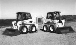
Description
Mauldin Asphalt Paver 1750-c Parts Manual
The information in this Operator’s Manual was written to give the owner/operator assistance in preparing, adjusting, maintaining and servicing of the Paver. More importantly, this manual provides an operating plan for safe and
proper use of the machine. Major points of safe operation are detailed in the SAFETY chapter of this manual. A
chart of standard hardware torques is located in the back of this manual.
The GEHL Company asks that you read and understand the contents of this manual COMPLETELY and
become familiar with your new machine, BEFORE attempting to operate it.
Mauldin Asphalt Paver 1750-c Parts Manual, Throughout this manual, information is provided which is set in italic type and introduced by the word NOTE.
Be sure to read carefully and comply with the message or directive given. Following this information will improve
your operating or maintenance efficiency, help you to avoid breakdowns or damage, and extend your machine’s life.
Mauldin Asphalt Paver 1750-c Parts Manual
Mauldin Asphalt Paver 1750-c Parts Manual A plastic container is provided on the unit for storing the Operator’s Manual. After using the Manual, please return it to the container and keep it with the unit at all times! If this machine is resold, Mauldin Company recommends that this Manual be given to the new owner.
“Right” and “left” are determined from a position standing on the Screed Platform and facing forward.
Our wide Dealership network stands by to provide you with any assistance you may require, including genuine
GEHL service parts. All parts should be obtained from or ordered through your GEHL Dealer.
Give complete
information about the part and include the model and serial numbers of your machine. Record the serial number
in the space provided on the previous page, as a handy record for quick reference.
GEHL Company reserves the right to make changes or improvements in the design or construction of any part
without incurring the obligation to install such changes on any unit previously delivered.
TABLE OF CONTENTS
ITEM PAGE
Quick Order Page ………………………………………………………………….. 2
Engine Enclosure…………………………………………………………………… 3
Engine Compartment ……………………………………………………………… 4
Engine Assembly – Left Side …………………………………………………… 5
Engine Assembly – Right Side…………………………………………………. 6
Hopper Assembly – Left Side…………………………………………………… 7
Hopper Assembly – Right Side ………………………………………………… 8
Hopper Assembly – Center……………………………………………………… 9
Screed Assembly – Front………………………………………………………… 10
Screed Assembly – Rear ………………………………………………………… 11
Flight Chain Assembly ……………………………………………………………. 12
Vibrator Assembly………………………………………………………………….. 13
Track Assembly……………………………………………………………………… 14
Idler Assembly……………………………………………………………………….. 14
Drive Assembly ……………………………………………………………………… 14
Battery Assembly …………………………………………………………………… 15
Propane Assembly…………………………………………………………………. 15
Electrical System Schematic……………………………………………………. Appendix A
Main Hydraulic Circuit Schematic……………………………………………… Appendix B
Feeder System Hydraulic Circuit Schematic ………………………………. Appendix C
Cylinder Hydraulic Circuit Schematic ………………………………………… Appendix D


Reviews
There are no reviews yet.