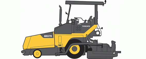
Description
Volvo ABG5770 Brake Service Repair Manual
Volvo Abg5770 Repair Manual
Abg5770, Abg5870
Abg6870
Chapter By Chapter List
0 – General
1 – Standard Parts, Service
2 – Engine With Mounting And Equipment
3 – Elec. Framework; Warning System; Information System; Instruments
4 – Power Transmission
5 – Brake
6 – Steering
7 – Frame; Springs; Damping; Axle Suspension; Wheel_Track Unit
8 – Machinery House; Cab; Exterior Trim Parts Anywhere
9 – Hydraulic System; Digging_Handling_Grading Equipm.; Misc Equipm
Complete Authority Administration Manual For Volvo Wheeled Paver Abg5770, Abg6870 With All The Shop Data To Keep Up, Analytic, Fix, Revamp/Reconstruct Like Proficient Mechanics. Volvo Abg5770 Service Manual
Complete Volvo Wheeled Paver Abg5770 Workshop Administration And Fix Manual Incorporates:
Numbered Chapter By Chapter Guide Simple To Utilize So You Can Discover The Data You Need Quickly.
Detailed Sub-Steps Develop Fix Methodology Data
Numbered Guidelines Manage You Through Each Fix System Bit By Bit.
Troubleshooting And Electrical Help Systems Are Joined With Itemized Wiring Outlines For Usability.
Notes, Alerts, And Admonitions All Through Every Section Pinpoint Basic Data.
Bold Figure Number Assistance You Rapidly Coordinate Outlines With Directions.
Detailed Outlines, Drawings, And Photographs Direct You Through Each Method.
Enlarged Inset Causes You To Distinguish And Look At Parts In Detail.
[Wp_Estore_Buy_Now_Fancy Id=3062]
[Wp_Estore_Cart_Fancy1_When_Not_Empty]
Volvo Abg5770 Service Repair Manual
Abg 8820
0 – General
00 – Description; Complete Machine
Description
03 – Specifications
Component Locations
Conversion Tables
Volvo Standard Tightening Torques
05 – Transport Instruction
Machine, Transporting
Traveling On Public Roads
07 – Standard Time
Operation Numbers For Additional Work
08 – Tool
E-7008
E-7016
Volvo ABG5770 Brake Service Repair Manual
1 – Standard Parts, Service
16 – Lubricant; Fuel; Other Fluid
17 – Service
Air Intake Hose, Changing
All-Weather Roof Pump Oil, Changing
Alternative Fuels
Arrival Inspection, According To Inspection Programme
Auger Bearing Protector, Changing
Auger Bearing Protector, Checking
Auger Bearings, Checking
Auger Bearings, Greasing
Auger Box, Draining
Auger Drive Chain Tension, Adjusting
Auger Drive Chain Tension, Checking
Battery Terminals, Cleaning
Bolted Joints, Check Tightening Torque
Central Lubrication Grease, Filling
Central Lubrication Hoses, Checking
Central Lubrication Level, Checking
Charge Air Cooler, Draining
Conveyor Drive Chain Tension, Adjusting
Conveyor Drive Chain Tension, Checking
Conveyor Drive Shaft, Checking
Conveyor Drive Shaft, Greasing
Conveyor Tension, Adjusting
Conveyor Tension, Checking
Coolant, Draining
Coolant, Filling
Coolant Level, Checking
Coolant
Coolant’S Freezing Point, Check
Delivery Inspection, According To Inspection Programme
Drive Lever And Operating Keys, Checking
Electric Welding
Emulsion Spraying System, Cleaning
Engine Air Cleaner Primary Filter, Changing
Engine Air Cleaner Primary Filter, Cleaning
Engine Belt, Replacing_{05-53-39}
Engine Belt, Replacing_{05-54-20}
Engine Belt Tension, Adjusting_{05-55-04}
Engine Belt Tension, Adjusting_{05-55-42}
Engine Belt Tension, Checking_{05-56-32}
Engine Hosing Connections, Checking
Engine Leakage, Checking
Engine Monitoring Warning System, Checking
Engine Mounts, Checking
Engine Oil, Drain
Engine Oil, Filling
Engine Oil Filter, Replacing
Engine Oil Level, Checking
Fuel Fine Filter, Changing
Fuel Prefilter, Changing
Fuel System, Air Bleeding
Fuel Tank Strainer, Cleaning
Generator Screed Heating Belt, Changing
Generator Screed Heating Belt Tension, Adjusting
Generator Screed Heating Belt Tension, Checking
Hopper Hinges, Inspecting
Hydraulic Cylinders, Checking
Hydraulic Hoses, Inspecting
Hydraulic Oil, Draining
Hydraulic Oil, Filling
Hydraulic Oil Level, Checking
Hydraulic Oil Return Filter, Changing
Hydraulic Tank Ventilation Filter, Changing
Lubricants, Service Capacities And Intervals_{07-59-16}
Lubricants, Service Capacities And Intervals_{08-00-34}
Lubrication
Main Control Unit, Checking
Maintenance Of Stored Machines, According To Inspection Programme
Maintenance Service, As Required
Maintenance Service, Every 1000 Hours
Maintenance Service, Every 100 Hours
Maintenance Service, Every 10 Hours
Maintenance Service, Every 1500 Hours
Maintenance Service, Every 2000 Hours_{07-52-58}
Maintenance Service, Every 2000 Hours_{07-53-15}
Maintenance Service, Every 3000 Hours
Maintenance Service, Every 4000 Hours
Maintenance Service, Every 500 Hours
Maintenance Service, First 100 Hours
Noise Absorbing Mats, Replacing
Parking Brake, Checking
Particulate Filter, Checking
Particulate Filter, Cleaning
Pump Distributor Gear Breather Filter, Replacing
Pump Distributor Gear Oil, Draining
Pump Distributor Gear Oil, Filling
Pump Distributor Gear Oil Level, Checking
Radiator, Cleaning
Ride-Levelling Cylinders, Adjusting
Ride-Levelling Cylinders, Checking
Road Lighting System, Checking
Road Scrapers, Adjusting
Road Scrapers, Checking
Screed Control Unit, Checking
Service
Service Position 1
Steering, Greasing
Switch Cabinet, Checking
Towing Arms Bearings, Greasing
Towing, Measures
Travel Gearbox Oil, Draining
Travel Gearbox Oil, Filling
Tyres, Checking Air Pressure
Valve Clearance Adjustment
Warning Devices, Checking
Washing, External Cleaning
Water Separator, Cleaning
Water Separator, Draining
Wheel Nuts Torque, Checking
19 – General
Ce-Marking, Emc-Directive
Checklist After A Fire Or Heat Exposure
Decontamination
Environmental Handling For The Future
Environmentally Hazardous Fluids
Environmentally Safe Handling
Health Hazards With Paint, Plastics And Rubber
Safety Concerns Everybody!
Safety During Work On Machines
Safety Rules When Servicing
Safety When Handling Oils And Fuel
Safety When Lifting And Supporting The Machine
Safety When Working On Hydraulic Systems
Safety When Working With Batteries
Service Position 1
Service Position 2
Service Position 3
Starting With Booster Batteries
Waste Handling
Working On The Electrical System Of The Machine
Volvo Abg5770 Service Repair Manual
2 – Engine With Mounting And Equipment
20 – General
Engine Belts, Specifications
Engine, Capacities
Engine, Description
Engine Oil Pressure
Fuel Tank, Capacities
Injection System, Specifications
21 – Engine
Engine, Specifications
23 – Fuel System
Fuel System, Specifications
25 – Inlet & Exhaust System
Diesel Particulate Filter System, Description
26 – Cooling System
Thermostat, Specifications
3 – Electrical; Warning; Information; Instruments
30 – General
10001 Restart Ecu
10020 No Valid Module Number
10050 Software Ecu [X] Check Machine Model
10100 Standard Parameter Ecu
10200 Check Option Parameter
10 Message Database Too Large – Automatically Saved
11 Internal Database Error
13 Error When Reading The Retain Values
14 Error When Writing The Retain Values
15001 Error Could Not Be Entered In Error Array
15 Error In Can Connection To Control Panel
16 Error When Reading The Machine No
17 Error When Writing The Machine No
1 Stop On External Control Panel [Left _ Right] Has Been Actuated!
21001 Ecu [X] Temperature [X] 302260C
21100 Module [X] Error, Internal Voltage Measurement V
21104 Control Unit Voltage Too Low
21105 Voltage Control Unit Too High
22001 Perform Brake Test
22002 Brake Test Succesfull
22003 Brake Test Not Succesfull!
22011 Stop Machine!
22012 Stop Request Canceled
2 Error On Control Panel Mcu!
3 Control No. [X] Reports Fault!
4001 Error On Sensor Travel Drive [Left _ Right]!
4011 Error, Steering Sensor Signal V
4101 Error, Pressure Switch Paving Speed!
4102 Error, Pressure Switch Transport Speed!
4103 Error, Pressure Switch Feed Pressure!
4104 Error, Pressure Sensor Rear-Wheel-Drive Ma
4201 Error, Pressure Sensor On Pump Front-Wheel-Drive Ma
4202 Error, Pressure Sensor Hopper Load Ma
4301 Error, Drive Lever Switch Forwards
4302 Error, Drive Lever Switch Reverse
4303 Error On The Drive Lever
4304 Internal Error, Drive Lever!
4305 Can Error, Drive Lever No. !
4306 Can Error On The Drive Lever
4 Caution System Is Working In Auxiliary Control!
5001 Diesel Engine, Coolant Level Too Low 302260C!
5002 Diesel Engine, Oil Pressure Too Low Bar
5003 Diesel Engine, Coolant Temperature To High 302260C!
5004 Diesel Engine, Charging Air Temperature Too High 302260C!
5005 Diesel Engine, Error On Speed Sensor 1_Min!
5006 Diesel Engine, Faulty Charge Air Pressure Sensor Bar!
5007 Diesel Engine, Faulty Oil Pressure Sensor Bar!
5008 Diesel Engine, Faulty Coolant Temperature Sensor 302260C!
5009 Diesel Engine, Faulty Charge Air Temperature Sensor 302260C!
5010 Fuel Low Pressure Beyond The Specified Range
5011 Fuel Low-Pressure Sensor Cable Break Or Short Circuit
5012 Air Filter Differential Pressure Sensor Voltage Outside The Target Range
5013 Battery Voltage Below A Specified Range
5014 Battery Above The Specified Range
5015 Fuel Temperature Above The Specified Range
5016 Fuel Temperature Sensor Cable Break Or Short Circuit
5017 Oil Temperature Above The Target Range
5018 Oil Temperature Sensor Cable Break Or Short Circuit
5019 Engine Stop Request Ignored By Operator
5020 Diesel Fuel On Reserve Level!
5021 Diagnosing Lamp Error Ems
5022 Emr Main Relay Short Circuit Pr Emergency Stop (Pin )
5023 Emr Main Control Relay Short Circuit
5024 Main Relay Short Circuit Or Emergency Stop
5025 Main Control Relay Short Circuit 24 Volt
5030 Error Common Rail Pressure Valve Stop And Restart The Machine
5040 Emr Connection Interrupted
5050 Emr, Can Bus Controller
5051 Emr, Can Interface
5052 Emr, Bus Error
5053 Emr, Write Eeprom
5054 Emr, Programme Test
5055 Emr, Ram Test
5056 Emr, Internal Electric Power Supply
5057 Emr, Internal Temperature
5058 Emr, Atmospheric Pressure
5059 Emr, Read Eeprom
5060 Emr, Batch Overflow
5061 Emr, Internal Error
5070 Unknown Emr Error!
5080 Error Emr, Fmi And Spn
5090 Check Motor Identification
5100 Generator Is Not Charging [X] V!
5200 Error, Heating Isolation!
5210 Error, Voltage L1 [X] V
5211 Error, Voltage L2 [X] V
5212 Error, Voltage L3 [X] V
5213 Error, Voltage N [X] V
5220 Error, Temperature Sensor [X] N302260C!
5 Errors When Reading The Parameters
6001 Error Return Filter 1
6002 Error Return Filter 2
6003 Hydraulic Oil Temperature Too High [X] 302260C!
6004 Error, Hydraulic Oil Temperature Sensor!
6005 Check Hydraulic Oil Level
6011 Check The Diesel Exhaust Filter!
6012 Air Filter Dirty!
6013 Fault Diesel Filter
6014 Error, Water Saparator Sensor
6021 Central Lubrication, Grease Tank Empty!
6022 Central Lubrication, No Grease Supply
6200 Augers [Left _ Right] Operating With Ultrasonic Sensors
6201 Augers [Left _ Right] Operating Without Ultrasonic Sensors!
6202 Conveyors Operating With Ultrasonic Senors
6203 Conveyors Operating Without Ultrasonic Sensors
6210 Conveyors [Left _ Right] Operating With Ultrasonic Sensors
6211 Conveyors [Left _ Right] Operating Without Ultrasonic Sensors!
6220 Error, Conveyor Sensor [Left _ Right]!
6230 Error, Auger Sensor [Left _ Right]!
6300 Error, Tamper Speed Sensor
6320 Error, Vibration Speed Sensor
6 Error When Writing The Parameters
7001 Undefined Error!
7002 Module No. [X] Solenoid, Drive Pump Lh Forward
7003 Module No. [X] Solenoid, Drive Pump Lh Reverse
7004 Module No. [X] Solenoid, Drive Pump Rh Forward
7005 Module No. [X] Solenoid Drive Pump Rh Reverse
7010 Module No. [X] Solenoid, Transport Speed
7011 Solenoid, Travel Drive Motor Lh
7012 Magnet Motor Drive Right
7013 Solenoid, Paving Speed
7014 Solenoid, Hydraulic Differential
7015 Solenoid, Rear Axle Load Relief
7020 Solenoid, Pump, Front Wheel Drive
7021 Solenoid, Flow Divider, Front Wheel Drive
7022 Solenoid, Free-Wheeling On Front Wheel Drive
7023 Solenoid, Return Flow Front Wheel Drive
7030 Solenoid, Tampers
7032 Solenoid, Vibration
7051 Solenoid, Screed Floating Mode
7053 Solenoid, Screed Assist
7054 Solenoid, Screed Load Device
7055 Solenoid, Screed Anti-Climbing Lock
7056 Solenoid, Screed Raise
7057 Solenoid, Screed Lower
7058 Solenoid, Screed Anti-Climbing Lock
7059 [Open Circuit _ Short Circuit _ Overcurrent] Solenoid, Screed Raise_Lower
7070 Solenoid, Crown Control Raise
7071 Solenoid, Crown Control Lower
7080 Solenoid, Hopper Close
7081 Solenoid, Hopper Open
7082 Solenoid, Hopper Lock Rh
7083 Solenoid, Hopper Lock Lh
7100 Solenoid, Auger Lh
7101 Solenoid, Auger Rh
7102 Solenoid, Auger Reverse Lh
7103 Solenoid, Auger Reverse Rh
7104 Solenoid, Augers Lower
7105 Solenoid, Augers Raise
7110 Solenoid, Conveyor Lh
7111 Solenoid, Conveyor Rh
7112 Solenoid, Conveyor Reverse Lh
7113 Solenoid, Conveyor Reverse Rh
7120 Warning Flashers Vario Screed
7121 Solenoid, Variomatic Lh Retract
7122 Solenoid, Variomatic Lh Extend
7123 Solenoid, Variomatic Rh Retract
7124 Solenoid, Variomatic Rh Extend
7140 Magnet Extractor!
7150 Solenoid, Cylinder Pressure
7160 Solenoid, Brake
7170 Solenoid, Central Lubrication System
7180 Solenoid, Cooling Fan Drive
7190 Solenoid, Tow Point Lh Raise
7191 Solenoid, Tow Point Lh Lower
7192 Solenoid, Tow Point Rh Raise
7193 Solenoid, Tow Point Rh Lower
7200 Solenoid, Warning Horn
7210 Solenoid, Engine Starter Motor
7220 Solenoid, Cold Start Valve
7300 Drive Current, Burner Control
7310 Error, Protection System 1
7311 Error, Protection System 2
7312 Error, Protection System 3
7313 Error, Protection System 4
7 Retransmit Parameters In Ecu [X]!
8 Ecu [X] In Emergency Control Has Been Restored
9 Control Panel Was Stopped By Internal Error!
Communication With Data Buses
Control Panel, Parameter Setting
Control Panel, Software Update
Control Unit, Software Update
Electrical System, Instructions
Epm Ii Service Tool
Error Code Information, Description
Error Codes, Build-Up
Inputs And Outputs Of The Control Units
Instruments And Controls, Overview_{04-53-24}
Instruments And Controls, Overview_{04-54-03}
Instruments And Controls, Overview_{04-58-36}
Instruments And Controls, Overview_{04-59-24}
Instruments And Controls, Overview_{05-10-12}
Instruments And Operating Controls, Specifications_{05-10-59}
Instruments And Operating Controls, Specifications_{05-11-16}
Menu 342200234Diagnosis342200235 – Start Display
Parameter Codes
Pre-Programmed Ecu, Replacing
Report
Software Parameters, Description
Switch Cabinet, Gas Screed Heating, Specifications
Trimming (Offset Adjustment)
31 – Battery
Battery, Charging
Battery, Description
Battery, Specifications
35 – Lighting
Lighting, Specifications
36 – Other Electrical Equipment
Emergency Stop Switch, Specifications
Engine Control Unit E-Ecu, Specifications
Vehicle Control Unit V-Ecu, Specifications
37 – Cable; Fuse; Relay
Battery Disconnector Switch, Description
Cable Markings
Central Ground Connections
Electrical Distribution Box, Fuses And Relays
Fuses
Wiring Diagram 10_{02-55-18}
Wiring Diagram 1_{03-03-37}
Wiring Diagram 1_{03-04-09}
Wiring Diagram 11_{02-54-18}
Wiring Diagram 11_{02-54-44}
Wiring Diagram 12_{02-53-43}
Wiring Diagram 13_{02-53-10}
Wiring Diagram 14_{02-52-34}
Wiring Diagram 15_{02-51-33}
Wiring Diagram 15_{02-52-01}
Wiring Diagram 16_{02-50-57}
Wiring Diagram 17_{02-49-54}
Wiring Diagram 17_{02-50-23}
Wiring Diagram 18_{02-48-57}
Wiring Diagram 18_{02-49-21}
Wiring Diagram 19_{02-48-00}
Wiring Diagram 19_{02-48-27}
Wiring Diagram 20_{02-46-57}
Wiring Diagram 20_{02-47-24}
Wiring Diagram 2_{03-02-31}
Wiring Diagram 2_{03-02-59}
Wiring Diagram 21_{02-45-55}
Wiring Diagram 21_{02-46-22}
Wiring Diagram 22_{02-44-57}
Wiring Diagram 22_{02-45-21}
Wiring Diagram 23_{02-43-56}
Wiring Diagram 23_{02-44-22}
Wiring Diagram 24_{02-43-03}
Wiring Diagram 24_{02-43-24}
Wiring Diagram 25_{02-42-28}
Wiring Diagram 26_{02-41-28}
Wiring Diagram 26_{02-41-54}
Wiring Diagram 27_{02-40-53}
Wiring Diagram 28_{02-40-20}
Wiring Diagram 29_{02-39-19}
Wiring Diagram 29_{02-39-47}
Wiring Diagram 30_{02-38-44}
Wiring Diagram 3_{03-01-53}
Wiring Diagram 31_{02-37-42}
Wiring Diagram 31_{02-38-10}
Wiring Diagram 32_{02-36-38}
Wiring Diagram 32_{02-37-07}
Wiring Diagram 33_{02-35-35}
Wiring Diagram 33_{02-36-04}
Wiring Diagram 34_{02-34-31}
Wiring Diagram 34_{02-34-59}
Wiring Diagram 35_{02-33-54}
Wiring Diagram 36_{02-32-48}
Wiring Diagram 36_{02-33-16}
Wiring Diagram 37_{02-31-41}
Wiring Diagram 37_{02-32-09}
Wiring Diagram 38_{02-31-09}
Wiring Diagram 39_{02-30-05}
Wiring Diagram 39_{02-30-32}
Wiring Diagram 40_{02-28-53}
Wiring Diagram 40_{02-29-22}
Wiring Diagram 4_{03-01-17}
Wiring Diagram 41_{02-27-44}
Wiring Diagram 41_{02-28-15}
Wiring Diagram 42_{02-26-44}
Wiring Diagram 42_{02-27-12}
Wiring Diagram 43_{02-25-45}
Wiring Diagram 43_{02-26-11}
Wiring Diagram 44_{02-25-12}
Wiring Diagram 45_{02-24-41}
Wiring Diagram 46_{02-24-09}
Wiring Diagram 47_{02-23-15}
Wiring Diagram 47_{02-23-37}
Wiring Diagram 48_{02-22-26}
Wiring Diagram 48_{02-22-47}
Wiring Diagram 49
Wiring Diagram 5_{03-00-14}
Wiring Diagram 5_{03-00-45}
Wiring Diagram 6_{02-59-11}
Wiring Diagram 6_{02-59-39}
Wiring Diagram 7_{02-58-03}
Wiring Diagram 7_{02-58-33}
Wiring Diagram 8_{02-56-58}
Wiring Diagram 8_{02-57-26}
Wiring Diagram 9_{02-55-52}
Wiring Diagram 9_{02-56-23}
Wiring Diagram Screed Heating 1_{02-21-08}
Wiring Diagram Screed Heating 1_{02-21-30}
Wiring Diagram Screed Heating 10
Wiring Diagram Screed Heating 2_{02-20-20}
Wiring Diagram Screed Heating 2_{02-20-41}
Wiring Diagram Screed Heating 3_{02-19-32}
Wiring Diagram Screed Heating 3_{02-19-53}
Wiring Diagram Screed Heating 4_{02-18-42}
Wiring Diagram Screed Heating 4_{02-19-04}
Wiring Diagram Screed Heating 5_{02-17-53}
Wiring Diagram Screed Heating 5_{02-18-15}
Wiring Diagram Screed Heating 6_{02-17-05}
Wiring Diagram Screed Heating 6_{02-17-26}
Wiring Diagram Screed Heating 7_{02-16-16}
Wiring Diagram Screed Heating 7_{02-16-37}
Wiring Diagram Screed Heating 8_{02-15-28}
Wiring Diagram Screed Heating 8_{02-15-49}
Wiring Diagram Screed Heating 9_{02-14-39}
Wiring Diagram Screed Heating 9_{02-15-01}
4 – Power Transmission
43 – Gearbox
Travel Gearbox, Assembling
Travel Gearbox, Disassembling
Travel Gearbox, Installing
Travel Gearbox, Removing
44 – Hydrostatic Drive
Drive Motor, Installing
Drive Motor, Removing
Travel Drive, Calibrating
6 – Steering
64 – Steering
Steering Angle Sensor, Adjusting
7 – Frame; Springs; Damping; Axle Suspension; Wheel_Track Unit
77 – Wheels; Tracks; Tyre; Hub; Drum
Front Wheel, Installing
Front Wheel, Removing
Rear Wheel, Installing
Rear Wheel, Removing
8 – Machinery House; Cab; Exterior Trim Parts Anywhere
84 – Trim Part; Outside; Glass; Sealing Moulding
Rear-View Mirror, Replacing
9 – Hydraulic System; Digging_Handling_Grading Equipment; Miscellaneous
90 – General
Hydraulic Diagram 10_{01-36-54}
Hydraulic Diagram 10_{01-37-15}
Hydraulic Diagram 11
Hydraulic Diagram 1
Hydraulic Diagram 2
Hydraulic Diagram 3
Hydraulic Diagram 4
Hydraulic Diagram 5_{01-41-14}
Hydraulic Diagram 5_{01-41-40}
Hydraulic Diagram 6_{01-40-05}
Hydraulic Diagram 6_{01-40-34}
Hydraulic Diagram 7_{01-38-57}
Hydraulic Diagram 7_{01-39-21}
Hydraulic Diagram 8
Hydraulic Diagram 9
91 – Working Hydraulic; Servo Hydraulics
Hydraulic Filter, Specification
Hydraulic Oil Tank – Description And Operation
98 – Function For Road Construction
Auger Flight, Installing
Auger Flight, Removing
Conveyor Cover, Installing
Conveyor Cover, Removing
Conveyor Drive Chain, Installing
Conveyor Drive Chain, Removing
Conveyor Drive Shaft, Installing
Conveyor Drive Shaft, Removing
Conveyor Idler Assembly, Disassembling And Assembling
Error Message In Display Unit
Front Apron Plate, Installing
Front Apron Plate, Removing
Generator Belt, Specifications
Generator Screed Heating, Specifications
Heating System, Description
Levelling Scales, Adjusting
Screed, Removing_{01-35-06}
Screed Spacer Blocks, Installing
Screed Spacer Blocks, Removing
Screed, Installing_{01-32-07}
Screed, Installing_{01-32-36}
Screed, Removing_{01-33-01}
Screed, Removing_{01-33-28}
Screed, Removing_{01-33-49}
Screed, Removing_{01-34-16}
Screed, Removing_{01-34-37}
Volvo Abg5770 Service Repair Manual


