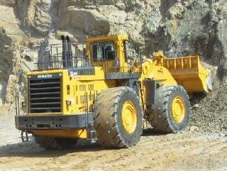
This Manual Consist Of The Folowing Three Separate Portions:
- Komatsu Wa800-3 Wheel Loader Service Repair Manual
- Komatsu Wa800-3 Wheel Loader Field Assembly Manual
- Komatsu Wa800-3 Wheel Loader Operation & Maintenance Manual
This Komatsu Wa800-3 Manual Contains Deep Information About Maintaining, Assembly, Disassembly And Servicing Your Komatsu Wa800-3 Wheel Loader. It Also Help You Realize Peak Performance Through Effective, Economical And Safe Machine Operation And Maintenance.
Machine Model Serial Number:
Wa800-3 – S/N: 50001 And Up
Wa800-3 Mount The Sa12V140-1 Engine.
For Details Of The Engine, See The 12V140-1 Series Engine Shop Manual.
The Komatsu Wa800-3 Service Repair Manual Contains Information And Data To This Model. Has Specs, Diagrams, And Actual Real Photo Illustrations, And Schemes, Which Give You Complete Step By Step Operations On Repair, Servicing, Technical Maintenance & Troubleshooting Procedures For Your Machine.
Komatsu Wa800-3 This Manual Offers Full Information You Need For Repair Your Machine. The Information In This Manual Will Enable You To Find Trouble And To Understand How To Repair And Maintain Your Machine Without Going Into Service.
The Operation & Maintenance Manual Describes Procedures For Operation, Handling, Lubrication, Maintenance, Checking, And Adjustment. It Will Help The Operator And Maintenance Personnel Realize Peak Performance Through Effective, Economical And Safe Machine Operation And Maintenance.
The Field Assembly Manual Provides You With Everything You Need To Know In Order To Assembly Your Komatsu Wa800-3 Wheel Loader Safely And Effectively. Step-By-Step Assembly Procedure, Parts Installation, Adjustment And Maintenance Procedure After Completion Of Assembly.
Service Repair Manual Contents: Komatsu Wa800-3
01 General
10 Structure And Function
20 Testing And Adjusting
30 Disassembly And Assembly
40 Maintenance Standard
90 Others
Operation & Maintenance Manual Contents:
- Foreword
- Safety Information
- Introduction
- Location Of Plates, Table To Enter Serial No. And Distributor
- Contents
Safety - General Precautions
- Precautions During Operation
- Precautions For Maintenance
- Position For Attaching Safety Labels
Operation - General View
- Explanation Of Components
- Operation
- Transportation
- Cold Weather Operation
- Long-Term Storage
- Troubleshooting
Maintenance Komatsu Wa800-3 - Guides To Maintenance
- Outlines Of Service
- Wear Parts List
- Use Of Fuel, Coolant And Lubricants According To Ambient Temperature
- Standard Tightening Torques For Bolts And Nuts
- Periodic Replacement Of Safety Critical Parts
- Maintenance Schedule Chart
- Service Procedure
- Specifications
Options, Attachments - Optional Parts And Attachments
- Selecting Buckets And Tires
- Handling Auto Shift System
- Handling Joystick Steering System
- Main Monitor Failure Display
- Handling Auto-Greasing System
- Air Conditioner
- Am / Fm Car Radio
- Am / Fm Radio-Cassete Stereo
Komatsu Wa800-3 Wheel Loader Field Assembly Manual
Field Assembly Instruction Komatsu Wa800-3
A-10 General Drawing And Transportation Specification Of Machine
A-20 Drawings Of Disassembled Units
A-30 Dimensions Of Removed Units
A-40 Layout Of Work Space
A-50 Necessary Tools
A-60 Necessary Equipments And Slings
A-70 List Of Oils, Greases, And Paints
A-80 Frame Stand
A-90 Field Assembly Schedule
Assembly Procedure
B-10A Coupling Front And Rear Frames
B-20A Installing Steering Pin
B-30A Installing Drive Shaft
B-40A Connecting Piping
B-50 Positioning Axles And Installing Supports
B-60 Positioning Bare Machine
B-70 Installing Rear Axle
B-80 Procedure For Installing Cover On Rear Axle Side
B-90 Installing Rear Axle Piping And Drive Shaft
B-100 Installing Front Axle
B-110 Installing Front Axle Piping And Connecting Drive Shaft
B-120 Installing Tires
B-130 Installing Fuel Tank
B-140 Installing Drain Line
B-150 Connecting And Fixing Fuel Piping
B-160 Fixing Drain Hoses Of Engine
B-170 Installing Ladder (Right)
B-180 Installing Floor And Cab Assembly
B-190 Connecting Air Conditioner Hoses
B-200 Connecting Brake Line
B-210 Connecting Ppc Line Hoses
B-220 Connecting Wiring Harnesses
B-230 Connecting Steering Oil Line
B-240 Connecting Throttle Cable
B-250 Installing Floor Cover
B-260 Connecting Windshield Washer Hose And Supplying Washer Fluid
B-270 Installing Battery Box Assembly
B-280 Wiring Battery
B-290 Wiring Diagram For Battery
B-300 Installing Battery Step
B-310 Installing Handrail (To Right Bracket)
B-320 Installing Handrail (To Right Battery Box And Top Hood)
B-330 Installing Rear Access Step
B-340 Installing Left Handrail
B-350 Installing Rear View Mirrors
B-360 Installing Muffler Pipe
B-370 Installing Counterweight
B-380 Installing Front Lamp Assembly
B-390 Installing Rops Canopy Assembly
B-400 Installing Antenna And Working Lamp
B-410 Installing Floor Mat
B-420 Installing Front Fenders
B-430 Procedure For Starting Engine
B-440 Installing Boom Assembly
B-450 Connecting Remote Grease Tubes
B-460 Preparing For Installing Bucket
B-470 Procedure For Installing Bucket
B-480 Adjusting Bucket Positioner
B-490 Adjusting Boom Kick-Out
B-500 Adjusting Drive Force Up Switch
B-510 Procedure For Bleeding Air From Work Equipment Circuit
Ajss Specification (If Equipped)
Appendix
Field Assembly Inspection Report

