John Deere 325SL Backhoe Loader Repair Technical Manual (S.N after C273920 – C390995)
Table of Contents
(Repair Technical Manual – TM13308X19)
Section 00—General Information
Group 0001—Safety
Group 0003—Torque Values
Section 01—Wheels
Group 0110—Powered or Non-Powered Wheels and Fastenings
Section 02—Axles and Suspension Systems
Group 0225—Input Drive Shafts and U-Joints
Group 0240—Powered Wheel Axle (MFWD)
Group 0250—Axle Shaft, Bearings, and Reduction Gears
Section 03—Transmission
Group 0300—Removal and Installation
Group 0350—Gear, Shafts, and Power Shift Clutches
Group 0360—Hydraulic System
Section 04—Engine
Group 0400—Removal and Installation
Section 05—Engine Auxiliary System
Group 0505—Cold Weather Starting Aids
Group 0510—Cooling Systems
Group 0520—Intake System
Group 0530—Exhaust Systems
Group 0560—External Fuel Supply Systems
Section 06—Torque Converter
Group 0651—Turbine, Gears, and Shaft
Section 09—Steering System
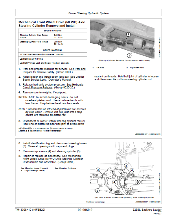
Group 0920—Power Steering
Group 0960—Power Steering Hydraulic System
Section 10—Service Brakes
Group 1011—Active Elements
Group 1015—Controls Linkage
Group 1060—Hydraulic System
Section 11—Park Brake
Group 1111—Active Elements
Section 16—Electrical System
Group 1600—Removal and Installation
Group 1675—System Controls
Section 17—Frame or Supporting Structure
Group 1740—Frame Installation
Group 1749—Chassis Weights
Section 18—Operator’s Station
Group 1800—Removal and Installation
Group 1810—Operator Enclosure
Group 1821—Seat and Seat Belt
Group 1830—Heating and Air Conditioning
Section 19—Sheet Metal and Styling
Group 1910—Hood or Engine Enclosure
Group 1913—Miscellaneous Shields
Group 1921—Grille
Section 20—Safety and Convenience
Group 2001—Radio
Group 2004—Horn and Warning Devices
Section 21—Main Hydraulic System
Group 2160—Hydraulic System
Section 31—Loader
Group 3102—Bucket
Group 3115—Controls Linkage
Group 3140—Frames
Group 3160—Hydraulic System
Section 33—Backhoe
Group 3302—Bucket
Group 3315—Control Linkage
Group 3340—Frames
Group 3360—Hydraulic System
Section 99—Dealer Fabricated Tools
Group 9900—Dealer Fabricated Tools
(Operation and Test Manual – TM13307X19)
Section 9000—General Information
Group 01—Safety
Section 9001—Diagnostics
Group 01—General Information
Group 10—Engine Control Unit (ECU) Diagnostic Trouble Codes
Group 20—Standard Display Monitor (SDM) Diagnostic Trouble Codes
Group 30—Transmission Control Unit (TCU) Diagnostic Trouble Codes
Group 40—Vehicle Control Unit (VCU) Diagnostic Trouble Codes
Group 50—Auxiliary Valve Controller (AVC) Diagnostic Trouble Codes
Group 60—Sealed Switch Module (SSM) Diagnostic Trouble Codes
Group 70—Vehicle Control Unit 2 (VC2) Diagnostic Trouble Codes
Section 9005—Operational Checkout Procedure
Group 10—Operational Checkout Procedure
Section 9010—Engine
Group 05—Theory of Operation
Group 10—System Diagrams
Group 15—Diagnostic Information
Group 20—Adjustments
Group 25—Tests
Section 9015—Electrical System
Group 05—Theory of Operation
Group 10—System Diagrams
Group 15—Diagnostic Information
Group 16—Monitor Operation
Group 17—Diagnostic Test Box
Group 20—Adjustments
Group 25—Tests
Section 9020—Power Train
Group 05—Theory of Operation
Group 10—System Diagrams
Group 15—Diagnostic Information
Group 20—Adjustments
Group 25—Tests
Section 9025—Hydraulic System
Group 05—Theory of Operation
Group 10—System Diagrams
Group 15—Diagnostic Information
Group 20—Adjustments
Group 25—Tests
Section 9031—Heating and Air Conditioning
Group 05—Theory of Operation
Group 10—System Diagrams
Group 15—Diagnostic Information
Group 25—Tests
This manual is written for an experienced technician and Owners. Essential tools required in performing certain service work are identified in this manual and are recommended for use.
Read the safety messages in the introduction of this manual and the cautions presented throughout the text of the manual.
These manuals are divided in two parts: repair and operation and tests. Repair sections tell how to repair the components. Operation and tests sections help you identify the majority of routine failures quickly.
Information is organized in groups for the various components requiring service instruction. At the beginning of each group are summary listings of all applicable essential tools, service equipment and tools, other materials needed to do the job, service parts kits, specifications, wear tolerances, and torque values.