
Book Categories:





















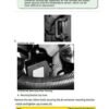
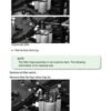
John Deere 18 Speed PST Component Technical Manual
$35.00
Language: English
Format: PDF
Publication: CTM168
Applicable for 18 speed PowerShift Transmission (PST)
- John Deere 18-speed PowerShift Transmission (PST) Component Technical Manual – 308 Pages
John Deere 18 Speed PST Component Technical Manual
The John Deere Hydraulic Cylinder Technical manuals CTM168 are divided as per the table of content. Repair sections tell how to repair the components. Diagnostic sections help you identify the majority of routine failures quickly.
Language: English
Format: PDF
Publication: CTM168
Applicable for 18 speed PowerShift Transmission (PST)
- John Deere 18-speed PowerShift Transmission (PST) Component Technical Manual – 308 Pages
Table of Content of the John Deere 18 speed PowerShift Transmission (PST) Manual
Foreword
Notice to the Dealer
01 – General Information
000 – Safety
Recognize Safety Information
Handle Fluids Safely—Avoid Fires
Prevent Battery Explosions
Prepare for Emergencies
Prevent Acid Burns
Handle Chemical Products Safely
Avoid High-Pressure Fluids
Park Machine Safely
Support Machine Properly
Wear Protective Clothing
Work in Clean Area
Service Machines Safely
Work In Ventilated Area
Illuminate Work Area Safely
Replace Safety Signs
Use Proper Lifting Equipment
Avoid Harmful Asbestos Dust
Avoid Heating Near Pressurized Fluid Lines
Remove Paint Before Welding or Heating
Use Proper Tools
Construct Dealer-Made Tools Safely
Dispose of Waste Properly
Live With Safety
10 – General Information
Identification Plate
General Repair Procedures
Sealants and Adhesives Cross-Reference Chart
Sealing Instructions
Cold Weather Operation
Oil Temperature Warning Signal
Recommended Lubricants
Lubricant Storage
Mixing of Lubricants
Oil Analysis
Alternative and Synthetic Lubricants
Check and Service Transmission Regularly
Intervals For Changing Transmission Oil Filters
Fill The Transmission With Oil (Wheel Tractors Only)
Check Oil Lines and Fittings
Hydraulic Connections
Transmission Storage
Transmission Removal From Storage
Towing The Vehicle
02 – Repair and Adjustments
15 – Transmission
Repair Stand Safety Precautions
Engine Repair Stand
Install Adapter to Engine Rollover Stand
Install Transmission Mounting Bracket
Install Transmission to Rollover Stand Bracket
Remove Transmission from Rollover Stand Bracket
Remove and Install Yoke
Replace Input and Output Shaft Seals (In Tractor)
Replace Bearing Retainer O-Ring Seals
20 – Electrical
Remove and Install Wiring Harness Bracket
Replacing the Transmission Wiring Harness
Front Housing Sensors and Ports
Rear Housing Sensors and Ports
Proportional Solenoid Identification – Left Side
Proportional Solenoid Identification – Right Side
Install Proportional Solenoid Valve
Remove and Install Input and Cylinder Speed
Magnetic Pickup Sensors
Remove and Install Fifth Stage Magnetic Pickup Sensor (Speed)
Remove and Install Output Magnetic Pickup Sensors
Remove and Install Oil Filter Head Pressure Switch
Remove and Install System Pressure Sensor
Remove and Install Temperature Sensor
25 – Hydraulics
System Components
Remove and Install Suction Screen
Remove and Install Oil Filter
Remove and Install Oil Filter Inlet Tube
Oil Filter Head
Remove Oil Filter Switch
Disassemble and Assemble Filter By-Pass Valve
Remove, Repair and Install Oil Filter Head
Remove, Repair and Install Main Regulator Valve
Remove and Install Lube Relief Bypass Valve
Remove and Install Cooler Relief Bypass Valve
Remove Oil Level Sight Glass (Wheel Tractors Only)
Repair Oil Level Sight Glass (Wheel Tractors Only)
Install Oil Level Sight Glass (Wheel Tractors Only)
30 – Pump Drive
Remove and Install Oil Line to Input Bearing
Remove and Install Transmission Vent Fitting
Remove Pump Drive Cover
Disassemble and Assemble Pump Drive Cover
Install Pump Drive Cover
Remove, Repair and Install Oil Pump Gear Assembly
Remove Transmission Oil Pump
Disassemble, Inspect and Assemble Transmission Oil Pump
Install Transmission Oil Pump
Remove and Install Pump Drive Input Gear
35 – Housings, Geartrain and Clutch Shafts
Remove Rear Housing With Internal Park Brake
Disassemble Rear Housing
Remove Clutch Shaft Sealing Ring Sleeve Old Style
Rear Housing Design
Install Bore Sleeves Old Style Rear Housing Design
Remove Clutch Assemblies
Exploded View— Output Shaft Without Internal Park Brake
Exploded View— Output Shaft With Internal Park Brake
Remove and Install Axle Pump Stand Pipe
Remove, Disassemble and Assemble Output Shaft Assembly
Remove Suction Tube Old Style Rear Housing
Remove Suction Tube
Install Output Shaft Assembly
Install Suction Tube Old Style Rear Housing
Install Suction Tube
Remove and Install Output Shaft Oil Dam
Exploded View—First Stage Shaft Assembly (Input Shaft)
Exploded View—Second Stage Clutch Shaft Assembly
Cross-Sectional View—Second Stage Clutch Shaft Assembly
9620 Series Exploded View—Second Stage Clutch Shaft Assembly
9620 Series Cross-Sectional View—Second Stage
Clutch Shaft Assembly
Exploded View—Third Stage Clutch Shaft Assembly
Cross-Sectional View—Third Stage Clutch Shaft Assembly
9620 Series Exploded View—Third Stage Clutch Shaft Assembly
9620 Series Cross-Sectional View—Third Stage Clutch Shaft Assembly
Exploded View—Fourth Stage Clutch Shaft Assembly
Cross-Sectional View—Fourth Stage Clutch Shaft Assembly
9620 Series Exploded View—Fourth Stage Clutch Shaft Assembly
9620 Series Cross-Sectional View—Fourth Stage Clutch Shaft Assembly
Exploded View—Fifth Stage Clutch Shaft Assembly
Cross-Sectional View—Fifth Stage Clutch Shaft Assembly
9620 Series Exploded View—Fifth Stage Clutch Shaft Assembly
9620 Series Cross-Sectional View—Fifth Stage Clutch Shaft Assembly
Exploded View—Sixth Stage Clutch Shaft Assembly
Cross-Sectional View—Sixth Stage Clutch Shaft Assembly
9620 Series Exploded View—Sixth Stage Clutch Shaft Assembly
9620 Series Cross-Sectional View—Sixth Stage Clutch Shaft Assembly
Exploded View—Seventh Stage Clutch Shaft Assembly
Cross-Sectional View—Seventh Stage Clutch Shaft Assembly
9620 Series Exploded View—Seventh Stage Clutch Shaft Assembly
9620 Series Cross-Sectional View—Seventh Stage Clutch Shaft Assembly
Disassembly and Assembly of Clutch Stage Shaft Assemblies
Disassemble and Assemble Second Stage Shaft Assembly
Disassemble and Assemble Fifth Stage Shaft Assembly
Disassemble and Assemble Seventh Stage Clutch Shaft Assembly
Disassemble and Assemble Sixth Stage Clutch Shaft Assembly Assembly
Disassemble and Assemble Third Stage Shaft Assembly
Install Clutch Assemblies
Install Rear Housing
Bearing Adjustment of Output Shaft Rear Housing
Internal Park Brake Assembly
Bearing Adjustments to Clutch Stage Shafts
Install Clutch Rotation Tools
Bearing Adjustment Of Fifth and Sixth Clutch
Stage Shaft Assemblies
Bearing Adjustment of Second, Third, Fourth and
Seventh Clutch Stage Shaft Assemblies
Bearing Adjustment of Output Shaft Front Housing
Bearing Adjustment of Input Shaft
John Deere 18 Speed PST Component Technical Manual
03 – Theory of Operation
20 – Theory of Operation
Transmission Operation
Gear Selection
Clutch Actuation
Gear Train Operation
Directional and Speed Clutch Operation
Range Clutch Operation
Internal Park Brake Operation
Transmission Hydraulic Diagram
Transmission Hydraulic Diagram – Internal Park
Brake Model
Transmission Pump Operation
Oil Filter Head
Main Regulator Valve
Main Regulator Valve Operation
Proportional Solenoid Valve Operation
Powershift Control Unit
05 – Tools and Other Materials
175 – Special Tools
Essential Tools For JDG9x20PST
Essential Tools for JDG9x20PSTWB
Other Material
195 – Dealer Fabricated Tools
DFRW146 Relief Valve Removal Tool
Guide Pins For Front And Rear Housing
Guide Pin for Shims, Caps and Pump Housings
06 – Specifications
205 – Torque Value
Metric Bolt and Screw Torque Values
Unified Inch Bolt and Screw Torque Values
Fittings, O’ring and Hose
READ THIS MANUAL carefully to learn how to service your John Deere 18 speed PowerShift Transmission (PST) manual correctly.
The John Deere Hydraulic Cylinder Technical manuals CTM168 are divided as per the table of content. Repair sections tell how to repair the components. Diagnostic sections help you identify the majority of routine failures quickly.
This manual was planned and written for the Service Department; its place is in the shop. Use the manual whenever in doubt about correct maintenance procedures. Use it as a text book for training new Service Department personnel who are unfamiliar with John Deere Tractors.
Technical Manuals are concise guides for specific-machines. Technical manuals are on-the-job guides-containing only the vital information needed for-diagnosis, analysis, testing, and repair.
John Deere 18 Speed PST Component Technical Manual
Only logged in customers who have purchased this product may leave a review.
Reviews
There are no reviews yet.