Book Categories:




















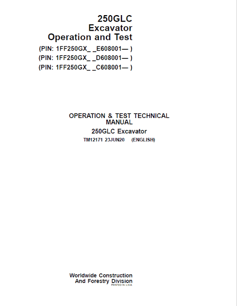
JD 250GLC Excavator Operation Test Service Manual TM12171
$69.99
JD 250GLC Excavator workshop diagnosis & test manual includes:
* Numbered table of contents easy to use so that you can find the information you need fast.
* Detailed sub-steps expand on repair procedure information
* Numbered instructions guide you through every repair procedure step by step.
* Troubleshooting and electrical service procedures are combined with detailed wiring diagrams for ease of use.
* Notes, cautions and warnings throughout each chapter pinpoint critical information.
* Bold figure number help you quickly match illustrations with instructions.
* Detailed illustrations, drawings and photos guide you through every procedure.
* Enlarged inset helps you identify and examine parts in detail.
JD 250GLC Excavator Operation Test Service Manual TM12171
- Specifications:
Brand: JD
Model: 250GLC
Serial Number: (PIN: 1FF250GX_ _E608001… , 1FF250GX_ _D608001… , 1FF250GX_ _C608001… )
Type of equipment: Excavator
Type Of Document: Technical Manual (Operation & Test)
Publication Numbers: All of these manual codes (TM12171, TM12195, TM12183, TM12316 ) are universally applicable to all product variations and regional builds within this specific machine family. TM12171, TM12195, TM12183, TM12316
Language: English
Format: PDF
JD 250GLC Excavator Repair Service Manual

JD 250GLC Excavator Operation Test Service Manual TM12171
**Table of Contents**
**Foreword**
**Technical Information Feedback Form**
**Section 9000: General Information**
**Group 01: Safety**
. Recognize Safety Information
. Follow Safety Instructions
. Operate Only If Qualified
. Wear Protective Equipment
. Avoid Unauthorized Machine Modifications
. Add Cab Guarding For Special Uses
. Inspect Machine
. Stay Clear of Moving Parts
. Avoid High-Pressure Fluids
. Avoid High-Pressure Oils
. Work In Ventilated Area
. Prevent Fires
. Prevent Battery Explosions
. Handle Chemical Products Safely
. Decommissioning — Proper Recycling and Disposal of Fluids and Components
. Exhaust Filter Ash Handling and Disposal
. Prepare for Emergencies
. Clean Debris from Machine
. Use Steps and Handholds Correctly
. Start Only From Operator’s Seat
. Use and Maintain Seat Belt
. Prevent Unintended Machine Movement
. Avoid Work Site Hazards
. Keep Riders Off Machine
. Avoid Backover Accidents
. Inspect and Maintain ROPS
. Operating or Traveling On Public Roads
. Avoid Machine Tip Over
. Use Special Care When Lifting Objects
. Add and Operate Attachments Safely
. Park and Prepare for Service Safely
. Service Cooling System Safely
. Remove Paint Before Welding or Heating
. Make Welding Repairs Safely
. Drive Metal Pins Safely
. Clean Exhaust Filter Safely
**Section 9001: Diagnostics**
**Group 10: Main Controller (MCZ) Diagnostic Trouble Codes**
. Main Controller (MCZ) Diagnostic Trouble Codes
. Controller Area Network 0 (CAN 0) Circuit Diagnostics
. Controller Area Network 1 (CAN 1) Circuit Diagnostics
. Interface Controller Area Network (N-CAN) Diagnostics
. Engine Controller Area Network (Engine CAN) Diagnostics
. 011000.02 – Abnormal EEPROM
. 011001.02 – Abnormal RAM
. 011002.02 – Abnormal A/D Converter
. 011003.03 – Abnormal Sensor Voltage
. 011004.02 – CAN Communication Error 1
. 011005.02 – CAN Communication Error 2
. 011006.02 – Engine Controller Communication Error
. 011007.02 – (CAN 0) Data Converter Communication Error 1
. 011008.02 – (CAN 1) Data Converter Communication Error 2
. 011009.02 – (CAN 0) Monitor Controller Communication Error 1
. 011010.02 – (CAN 1) Monitor Controller Communication Error 2
. 011100.02 – Abnormal Engine Speed
. 011101.03 / 011101.04 – Engine Control Dial Sensor Circuit High / Low
. 011200.03 / 011200.04 – Pump 1 Delivery Pressure Sensor Circuit High / Low
. 011202.03 / 011202.04 – Pump 2 Delivery Pressure Sensor Circuit High / Low
. 011206.03 / 011206.04 – Pump 1 Control Pressure Sensor Circuit High / Low
. 011208.03 / 011208.04 – Pump 2 Control Pressure Sensor Circuit High / Low
. 011301.03 / 011301.04 – Swing Pressure Sensor Circuit High / Low
. 011302.03 / 011302.04 – Boom Up Pressure Sensor Circuit High / Low
. 011303.03 / 011303.04 – Arm In Pressure Sensor Circuit High / Low
. 011304.03 / 011304.04 – Travel Pressure Sensor Circuit High / Low
. 011307.03 / 011307.04 – Front Attachment Pressure Sensor Circuit High / Low
. 011400 series – Pump 2 Control Rate Limit, Torque Control, Dig/Arm/Power Dig/Travel Speed Solenoid Feedback Codes
. 011457.02 – 2-Speed Activation Solenoid Disconnected
. 011458.02 – Selector Valve Solenoid Disconnected
. 011459.02 – Idle Stop Relay Circuit Malfunction
. 015011.03 / 015011.04 – Hydraulic Oil Temperature Sensor Circuit High / Low (Pilot)
. 015016.03 / 015016.04 – Right Analog Stroke Sensor Circuit High / Low
. 011810.03 / 011810.04 – Electric Lever Operating Pressure Sensor 1 High / Low
. 011812.02 / 011813.02 – OPT Electric Lever 1 Neutral / Abnormal Operation
. 011816 / 011817 series – OPT Solenoid 1 & 2 Feedback Codes
. 011901.03 / 011901.04 – Hydraulic Oil Temperature Sensor Circuit High / Low
. 020010.2 – Abnormal Exhaust Filter
. 020011.02 – Electric Lever Alarm
. 020062.02 – Hydraulic Oil Temperature Alarm
. 020303.02 – Electric Lever Pilot Cut Alarm
**Group 20: Engine Control Unit (ECU) Diagnostic Trouble Codes (Level 14 Controller)**
. Engine Control Unit (ECU) Diagnostic Trouble Codes (Level 14)
. 000171.03 / 000171.04 – Intake Air Temperature Sensor Out of Range High / Low
. 000647.05 / 000647.31 – Proportional Fan Speed Solenoid & Manual Reverse Mode
. 000898.09 – Engine Speed Request Not Received
. 001638.09 – Hydraulic Oil Temperature Message Not Received
. 020106.02 – Air Cleaner Restriction Alarm
**Group 21: Engine Control Unit (ECU) Diagnostic Trouble Codes (Level 21 Controller)**
. Engine Control Unit (ECU) Diagnostic Trouble Codes
. 000107.00 – Air Filter Differential Pressure High
. 000111.01 / 000111.18 – Coolant Level Low
. 000158.01 / 000627.18 – Battery Voltage Low / Below Normal
. 000190.00 – Engine Speed High
. 000647.05 / 000647.06 / 000647.16 – Proportional Fan Speed Valve Solenoid Codes
. 000676.03 / 000676.05 – Glow Plug Relay Output Codes
. 000898.09 – Requested Speed / Speed Limit
. 001110.31 – Engine Protection System Shutdown
. 001568.02 – Torque Curve Selection
. 001638.09 / 001639 series – Hydraulic Temperature & Fan Speed Codes
. 002000.13 / 002003.13 / 002017.13 – Security Violation Codes
. 002003.09 / 002005.09 / 002017.09 – CAN Timeout / Abnormal Update Rate
. 002146.09 – HCI Pump Message Missing
. 002883.03 / 002883.04 – Idle Switch Voltage Out of Range
. 003701.14 – Exhaust Filter Cleaning Not Required
. 0065372.05 / 065372.06 – Proportional Fan Speed Valve Solenoid Codes
**Group 30: Monitor Controller (DSZ) Diagnostic Trouble Codes**
. Monitor Controller (DSZ) Diagnostic Trouble Codes
. 013002.02 – ECU Communication Error
. 013003.02 / 013004.02 – Main Controller (MCZ) Communication Error 1 / 2
. 013005.02 / 013006.02 – Monitor Controller (DSZ) Communication Error 1 / 2
. 013007.02 – Machine Controller (BCZ) Communication Error
. 020113.02 – System Error Alarm
**Group 40: Information Controller (ICZ) Diagnostic Trouble Codes**
. Information Controller (ICZ) Diagnostic Trouble Codes
. 013311.03 / 013311.04 – Fuel Level Sensor Open / Shorted Circuit
. 013334.02 – Radiator Coolant Error
. 014001.02 – Flash Memory Read/Write Error
. 014002.02 – External RAM Read/Write Error
. 014003.02 – Abnormal EEPROM
. 014006.02 – Communication Terminal Communication Error
. 014008.02 – Abnormal Internal RAM
. 014021.02 / 014022.02 / 014023.02 – Communication Terminal / SIM Card / Security Errors
. 020101.02 – Engine Warning Alarm
. 020102.02 – Engine Oil Pressure Alarm
. 020103.02 – Alternator Alarm
. 020105.02 – Hydraulic Oil Filter Restriction Alarm
. 020109.02 – Pilot Control Shut-Off Lever Alarm
. 020110.02 – Fuel Filter Restriction Alarm
. 020133.02 – Crane Function Alarm
. 020137.02 – Exhaust Filter Alarm
. 020141.02 – Exhaust Temperature Alarm
. 020142.02 – Intake Air Temperature Alarm
. 020145.02 – Boost Temperature Increase Alarm
. 020146.02 – Fuel Temperature Increase Alarm
. 020149.02 – EGR Gas Temperature Alarm
**Group 50: Air Conditioner Controller (ACF) Diagnostic Trouble Codes**
. Air Conditioner Controller (ACF) Diagnostic Trouble Codes
. 11 / 12 – Air Recirculation Sensor Open / Short Circuit
. 13 / 14 – Ambient Air Temperature Sensor Open / Short Circuit
. 18 – Solar Radiation Sensor Short Circuit
. 21 / 22 – Air Conditioner Freeze Control Switch Open / Short Circuit
. 43 / 44 – Air Conditioner & Heater Servomotor Abnormal
. 51 – Air Conditioner High/Low Pressure Switch Abnormal
. 91 / 92 – Communication Error / CAN Bus Off Error
**Section 9005: Operational Checkout Procedure**
**Group 10: Operational Checkout Procedure**
. Operational Checkout
**Section 9010: Engine**
**Group 05: Theory of Operation**
. Engine Identification
. JD Engine
. Engine Fuel System Component Location
. Engine Cooling System Component Location
. Cold Weather Starting Aid
. Engine Speed Control System Operation
**Group 15: Diagnostic Information**
. JD Engine
**Group 20: Adjustments**
. JD Engine
**Group 25: Tests**
. JD Engine
. Radiator Temperature Differential Check
**Section 9015: Electrical System**
**Group 05: System Information**
. Electrical Diagram Information
**Group 10: System Diagrams**
. Explanation of Wire Markings
. Fuse and Relay Specifications
. System Functional Schematic, Component Location, and Wiring Diagram Master Legend
. System Functional Schematic
. Cab Harness (W1) Component Location & Wiring Diagram
. Machine Harness (W2) Component Location & Wiring Diagram
. Monitor Harness (W3) Component Location & Wiring Diagram
. Engine Harness (W4) Component Location & Wiring Diagram
. Engine Interface Harness (W5) Component Location & Wiring Diagram
. Front Engine Harness (W7) Component Location & Wiring Diagram
. Pump Harness (W8) Component Location & Wiring Diagram
. Exhaust Filter Parked Cleaning Switch Harness (W9)
. Service ADVISOR™ Remote (SAR) Harness (W10)
. Pilot Shutoff Switch Harness (W11)
. Service ADVISOR™ Remote Switch Resistor Harness (W12)
. Auxiliary Fuse Box Harness (W13)
. Heated Air Seat Harness (W14)
. Multi-Function Pilot Control Lever Harness (W15)
. Travel Alarm Cancel Switch Harness (W16)
. Attachment Harness (W17)
. Alternator Harness (W18)
. Rear Camera Harness (W19)
. Pilot Shutoff Valve Harness (W21)
. Auxiliary 3-Button Cancel Switch Harness (W22)
. Reversing Fan Switch Harness (W23)
. Seat Heater Switch Harness (W24)
. Travel Alarm Harness (W26)
. Starter Harness (W27)
. Starter Switch Harness (W29)
. 2-Speed Harness (W32)
. Intake Air Sensor Harness (W33)
. Fuel Dosing Harness (W34)
. Fuel Injector Harness (W38)
. Glow Plug Harness (W40)
. Heater and Air Conditioner Harness (W41)
. Alternator Jumper Harness (W42)
. Auxiliary Solenoid Harness (W61)
. Auxiliary Function Lever (AFL) Harness (W75 / W76)
. Modular Telematics Gateway (MTG) Harness (W6002)
. Satellite (SAT) Harness (W6003)
**Group 15: Sub-System Diagnostics**
. Controller Area Network (CAN) Theory of Operation
. Starting and Charging Circuit Theory of Operation
. Monitor Controller (DSZ) Circuit Theory of Operation
. Engine Control Unit (ECU) Circuit Theory of Operation
. Exhaust Aftertreatment Circuit Theory of Operation
. Main Controller (MCZ) Circuit Theory of Operation
. Machine Controller (BCZ) Circuit Theory of Operation
. Windshield Wiper and Washer Circuit Theory of Operation
. Lighting Circuit Theory of Operation
. Travel Alarm Circuit Theory of Operation
. Pilot Shutoff Circuit Theory of Operation
. Attachment Control Circuit Theory of Operation
JD 250GLC Excavator Operation Test Service Manual TM12171
**Group 16: Monitor Operation**
. Service Menu
. Troubleshooting
. Monitoring
. Controller Version
. Issued Warning Record
. Operation
. Machine Setting
. Monitor Setting
. Exhaust Filter
**Group 20: References**
. Reading Diagnostic Trouble Codes with Monitor Display
. Service ADVISOR™ Diagnostic Application & Connection Procedure
. Reading Diagnostic Trouble Codes with Service ADVISOR™
. MPDr Application & Connection Procedure
. Fuse / Relay / Pressure Sensor / Solenoid / Proportional Solenoid / Temperature Sensor / Alternator Tests
. Controller Area Network (CAN) Circuit Test
. Electrical Component Checks
. Battery / Rear Cover / Controllers (MCZ, BCZ, ECU, Data Converter, DSZ, ACF) Remove and Install
. Key Switch / Switch Consoles / Travel Alarm Remove and Install
. Heater Control Disable and Enable
. Connector Repair Procedures (DEUTSCH™, WEATHER PACK™, Metri-Pack™, CINCH™)
**Section 9020: Power Train**
**Group 05: Theory of Operation**
. Track Adjuster and Recoil Spring Operation
. Travel Gearbox Operation
**Group 15: Diagnostic Information**
. Noisy or Loose Track Chain
. Tight Track Chain
. Frequent Track Chain Sag Adjustment Required
. Excessive Oil Leakage From Front Idler, Track Rollers, or Carrier Rollers
. Bent Track Shoes
. “Popping” of Track
. Cracked Track Link
. Chipped Link Rails
. Individual Undercarriage Component Wear
. Measure Swing Bearing Wear
**Section 9025: Hydraulic System**
**Group 05: Theory of Operation**
. Hydraulic System Operation
. Fan Drive Hydraulic System Operation
. Pilot System Operation
. Pilot Pump, Pressure Regulating Valve and Filter Operation
. Pilot Shutoff Solenoid Valve Operation
. Pilot Control Valve Operation
. Travel Pilot Control Valve Operation
. Pilot Operation of Control Valve Operation
. Pilot Signal Manifold Operation
. Pump 1, Pump 2 and Drive Gearbox Operation
. Pump 1 and Pump 2 Regulator Operation
. Engine Speed Sensing Control Circuit Operation
. Control Valve Operation
. Control Valve Check Valves Identification and Operation
. Main Relief Valve Circuit Operation
. Circuit Relief and Anticavitation Valve Operation
. Travel Flow Combiner Valve Operation
. Auxiliary Flow Combiner Valve and Bypass Shutoff Valve Operation
. Boom Lower Meter-In Cut Valve Operation
. Boom / Dig / Arm / Bucket Regenerative Valve Circuit Operation
. Boom and Arm Reduced Leakage Valves Operation
. Arm 1 / Arm 2 / Bucket / Boom / Auxiliary Flow Rate Control Valve Circuit Operation
. Swing Reduction Gearbox / Swing Motor / Crossover Relief / Make-Up Check Valve / Damper Valve / Park Brake Release Circuit Operation
. Center Joint Operation
. Travel Motor and Park Brake Valve Operation
. Travel Motor Speed Circuit Operation
. Cylinder Operation
. Return Filter Operation
. Auxiliary System Operation (Pilot Control Valve, Flow Rate Select, Pressure Reducing, Secondary Relief, Selector Valve, Shuttle Valve, High Flow, Two Way, Two Pump Combined Flow, Low Flow Kits)
**Group 15: Diagnostic Information**
. All Hydraulic Functions Slow
. Hydraulic Oil Overheats
. No Hydraulic Functions
. No Hydraulic Functions—Electrical Checks
. Function Does Not Stop When Control Lever Released
. Load Drifts Down When Control Lever is in Neutral
. Load Falls When Control Valve is Actuated To Raise Load
. H/P (High Power) Function Does Not Operate
. Boom Down / Arm In Issues
. Swing Speed Slow During Arm In
. Boom Cannot Raise Track Off Ground
. Swing Function Issues (Both Directions / One Direction / Drift)
. Machine Freewheels Down an Incline
. Track Will Not Move / Machine Mistracks
. Machine Will Not Shift Into Fast (Rabbit) Speed
. Pump, Control Valve, Swing Motor, Pilot, Travel & Auxiliary Line Identifications and Schematics
. Hydraulic System Schematic & Component Location
**Group 25: Tests**
. Digital Thermometer & Pressure/Temperature Analyzer Installation
. General Hydraulic Oil Cleanup & Tank Pressure Release Procedures
. Hydraulic Oil Warm-Up Procedure
. Pilot Pressure Regulating Valve Test and Adjustment
. Control Valve Spool Actuating Pilot Pressure Test
. Dig / Arm / Power Dig / Travel Speed / Torque Control Solenoid Valve Tests
. Pump Control Pilot Pressure Signal Test
. Main Relief and Power Dig Valve Test and Adjustment
. Circuit Relief / Swing Motor Crossover / Travel Motor Crossover Relief Valve Tests
. Pump Regulator Tests (Minimum / Maximum Flow)
. Pump Flow Test & Comprehensive Pump Flow Test
. Swing Motor / Travel Motor Leakage Tests
. Cylinder Drift Test (Boom, Arm, Bucket)
. Upperstructure Drift Test
. Fan Drive Pump Flow Test & Fan Speed Test
**Section 9031: Heating and Air Conditioning**
**Group 05: Theory of Operation**
. Air Conditioning System Cycle of Operation
**Group 15: Diagnostic Information**
. No Air Flow From Heater and Air Conditioner Vents
. Air Conditioning System Does Not Operate
. Air Conditioning Does Not Cool / Runs Constantly Too Cold
. Interior Windows Continue to Fog
. Heater System Does Not Operate / Does Not Warm Cab
. Heater and Air Conditioner Component Location
**Group 25: Tests**
. Refrigerant Cautions and Proper Handling
. Heater and Air Conditioner Operational Checks
. Air Conditioner Compressor Clutch Test
. Refrigerant Leak Test
. Refrigerant Hoses and Tubing Inspection
. Air Conditioner Compressor Belt Check and Adjustment
. R134a Air Conditioning System Test
. Operating Pressure Diagnostic Chart
**Section 9900: Dealer Fabricated Tools**
**Group 99: Dealer Fabricated Tools**
. DFT1218 Split Flange Hose Cap
**JD 250GLC Excavator Operation & Test Service Manual – TM12171**


Reviews
There are no reviews yet.