
Book Categories:




















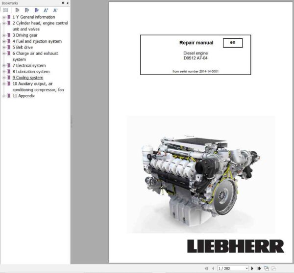
Liebherr Engine D9512 A7-04 Repair Manual 11387178
$49.99
This comprehensive manual is organized into numbered sections with a consistent “removing and installing” structure for each component, providing the technical depth required for professional engine repair.
Liebherr Engine D9512 A7-04 Repair Manual 11387178
- Brand: Liebherr
Type of Machine: Engine
Type of Manual: Repair Manual
Model: Liebherr D9512 A7-04 Engine
From Serial Number 2014-14-0001
Part Number: 11387178
Publication Date: 2015
Number of Pages: 282 Pages - Size: 13.56 MB
Format: PDF
Language: English
Liebherr D9512 Diesel Engine – Final Tier 4 Repair Manual
Liebherr Engine D9512 A7-04 Repair Manual
Contents
1 General Information
1.1 Structure of this manual
1.2 Important notes in this manual
1.3 Safety instructions
1.4 Safety instructions for working on the fuel and injection system
1.5 Safety instructions for working on the exhaust after-treatment system (SCR system)
1.6 Engine diagrams and engine components
1.7 Technical data
1.8 Standard torques and auxiliary materials
1.9 Fuel diagram
1.10 Lubricating oil diagram
1.11 Coolant diagram
1.12 Assigning the channels in the crankcase and the cylinder head
1.13 Transport device and fastening parts
1.14 Tools
2 Cylinder Head, Engine Control Unit and Valves
2.1 Removing and installing the cylinder head cover
2.2 Removing and installing the rocker arm bracket and push rods
2.3 Removing and installing the valve bridge
2.4 Removing and installing the cylinder head
2.5 Removing and installing the valve stem seal, valve springs, valves
2.6 Removing and installing the roller tappet
2.7 Removing and installing the camshaft
2.8 Removing and installing the camshaft bearing
3 Driving Gear
3.1 Removing and installing the piston with connecting rod and piston rings
3.2 Removing and installing the cylinder liner
3.3 Removing and installing the crankshaft attachments
3.4 Removing and installing the front crankshaft seal
3.5 Removing and installing the unit carrier
3.6 Removing and installing the intermediate wheel
3.7 Removing and installing the flywheel
3.8 Removing and installing the rear crankshaft seal
3.9 Removing and installing the crankshaft gear wheel
3.10 Removing and installing the flywheel housing
3.11 Removing and installing the crankshaft
4 Fuel and Injection System
4.1 Removing and installing the fuel lines
4.2 Removing and installing the injection line
4.3 Removing and installing the rail
4.4 Removing and installing the pressure pipe branch and injector
4.5 Removing and installing the fuel fine filter module (KSC module)
4.6 Removing and installing the high pressure pump
4.7 Removing and installing the high pressure pump drive
5 Belt Drive
5.1 Removing and installing the V-ribbed belt tensioning device alternator
5.2 Removing and installing the V-ribbed belt tensioning device air conditioning compressor
6 Charge Air and Exhaust System
6.1 Removing and installing the exhaust pipe
6.2 Removing and installing the exhaust manifold
6.3 Removing and installing the exhaust turbocharger
6.4 Removing and installing the heat shield
6.5 Removing and installing the air intake pipe
6.6 Removing and installing the charge air line
6.7 Removing and installing the connecting line
6.8 SCR exhaust after-treatment system
7 Electrical System
7.1 Removing and installing the heating flange
7.2 Removing and installing the alternator
7.3 Removing and installing the starter
7.4 Removing and installing sensors
7.5 Removing and installing the engine control unit
7.6 Removing and installing the engine control unit attachment
7.7 Replacing the cable harness
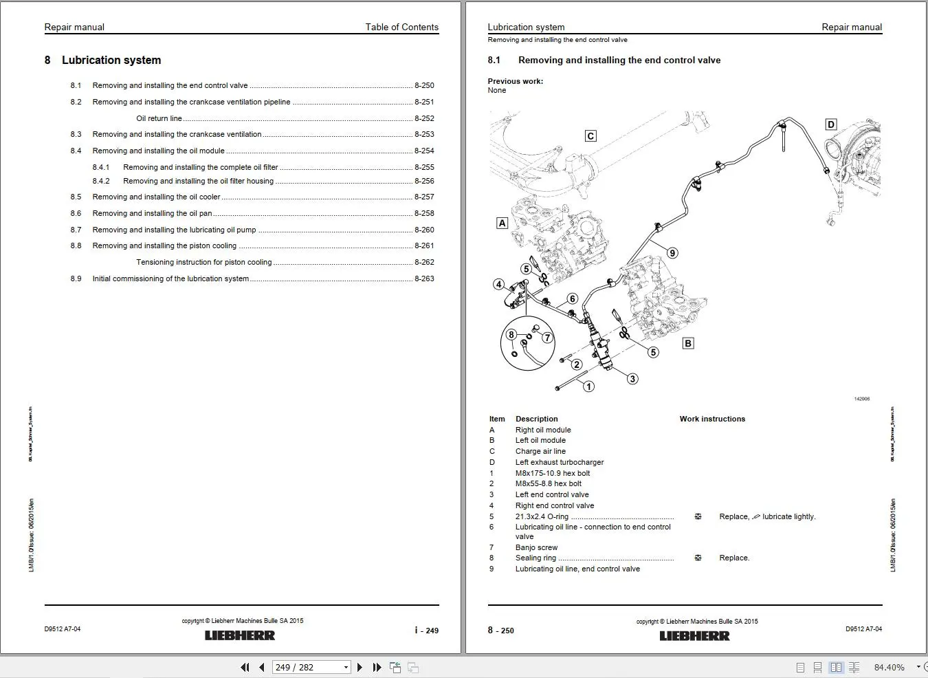
8 Lubrication System
8.1 Removing and installing the end control valve
8.2 Removing and installing the crankcase ventilation pipeline
8.3 Removing and installing the crankcase ventilation
8.4 Removing and installing the oil module
8.5 Removing and installing the oil cooler
8.6 Removing and installing the oil pan
8.7 Removing and installing the lubricating oil pump
8.8 Removing and installing the piston cooling
8.9 Initial commissioning of the lubrication system
9 Cooling System
Liebherr D9512 A7-04 Workshop Manual 282 Pages SCR Engine Guide
9.1 Removing and installing the ventilation line
9.2 Removing and installing the coolant manifold
9.3 Removing and installing the coolant pump
9.4 Removing and installing the thermostat housing
9.5 Removing and installing the thermostats
9.6 Check the thermostat
10 Auxiliary Output, Air Conditioning Compressor, Fan
10.1 Removing and installing the air conditioning compressor
11 Appendix
11.1 Symbols in this manual
11.2 Abbreviations used



Reviews
There are no reviews yet.