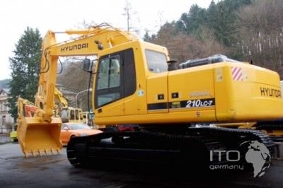
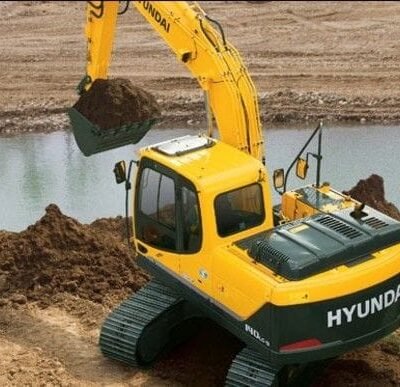
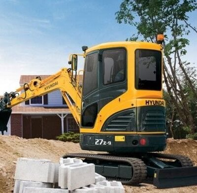
Hyundai Crawler Excavator Robex 210LC-7 Complete Manual
This collection contains the following products:
1. Hyundai Crawler Excavator Robex 210LC-7 R210LC-7 Service Manual
2. Hyundai Crawler Excavator Robex 210LC-7 R210LC-7 Operators Manual
1. Hyundai Crawler Excavator Robex 210LC-7 R210LC-7 Service Manual
The service manual has been prepared as an aid to improve the quality of repairs by giving the serviceman an accurate understanding of the product and showing him the correct way to perform repairs and make judgements. Make sure you understand the contents of this manual and use it to full dffect at every opportunity.
This service manual mainly contents the necessary technical information for operation performed in a service workshop.
This Service and Repair Manual Covers the following Models:
– Hyundai Robex 210LC-7 R210LC-7 Crawler Excavator
Robex 210LC-7 R210LC-7 Hyundai Crawler Excavator Service Manual
This service manual contains:
FOREWORD
INDEX
SECTION 1 GENERAL
Group 1 Safety Hints
Group 2 Specifications
SECTION 2 STRUCTUREND FUNCTION
Group 1 Pump Device
Group 2 Main Control Valve
Group 3 Swing Device
Group 4 Travel Device
Group 5 RCV Lever
Group 6 RCV Pedal
SECTION 3 HYDRAULIC SYSTEM
Group 1 Hydraulic Circuit
Group 2 Main Circuit
Group 3 Pilot Circuit
Group 4 Single Operation
Group 5 Combined Operation
SECTION 4 ELECTRICAL SYSTEM
Group 1 Component Location
Group 2 Electrical Circuit(up to # 1000).
Group 3 Electrical Component Specification.
Group 4 Connectors.
Group 5 Electrical Circuit(# 1001 and up, Tier 2).
SECTION 5 MECHATROMICS SYSTEM.
Group 1 Outline(up to # 1000).
Group 2 Mode selection System(up to # 1000).
Group 3 Automatic Deceleration System.
Group 4 Power Boost System.
Group 5 Travel Speed Control System.
Group 6 Automatic Warming Up Function.
Group 7 Engine Overheat Prevention Function.
Group 8 Anti-Restart System.
Group 9 Self-Diagnostic System.
Group 10 Engine Control System.
Group 11 EPPR(Electro Proportional Pressure Reducing) Valve.
Group 12 Prolix Switch(up to # 0179).
Group 13 Monitoring System.
Group 14 Outline(# 1001 and up, Tier 2).
Group 15 Mode selection system(# 1001 and up, Tier 2).
SECTION 6 TROUBLESHOOTING.
Group 1 Before troubleshooting.
Group 2 Mechanical and hydraulic System.
Group 3 Electrical System.
Group 4 Mechatronics System.
Group 5 Mechatronics System(# 1001 and up, Tier 2).
SECTION 7 MAINTENANCE STANDARD.
Group 1 Operational Performance Test.
Group 2 Major Components.
Group 3 Track and Work Equipment.
SECTION 8 DISASSEMBLY AND ASSEMBLY.
Group 1 Precaution.
Group 2 Tightening Torque.
Group 3 Pump Device.
Group 4 Main Control Valve.
Group 5 Swing Device.
Group 6 Travel Device.
Group 7 RCV Lever.
Group 8 Turning Joint.
Group 9 Boom, Arm and Bucket Cylinder.
Group 10 Undercarriage.
Group 11 Work Equipment.
SECTION 9 COMPONENT MOUNTING TORQUE.
Group 1 Introduction guide.
Group 2 Engine system.
Group 3 Electric system.
Group 4 Hydraulic system.
Group 5 Undercarriage.
Group 6 Structure.
Group 7 Work equipment.

