
Book Categories:




















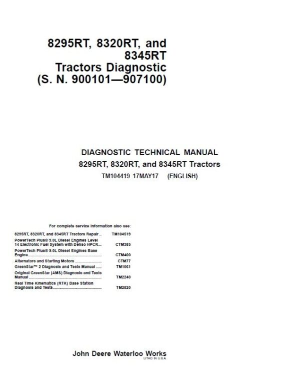
JD TM104419 Diagnostic Manual PDF
$69.99
Use the JD TM104419 Diagnostic Manual PDF, for maintenance planning, repair reference and equipment diagnostics, as applicable.
- Equipment / Model: JD TM104419 Diagnostic Manual PDF
- Format: Digital PDF
- Manual type: Technical reference
Useful for technicians, fleet maintenance teams and machinery owners.
JD TM104419 Diagnostic Manual PDF
JD 8295RT, 8320RT, 8345RT 8RT Tractor Diagnostic Technical Service Repair Manual TM104419
- Type Of Document: Diagnostic ManualBrands: JD
- Type of equipment: Tracked Tractor
- Model: 8295RT, 8320RT, 8345RT
- Heavy Tractors 8000-9000Series Serial Number: 900101-907100
JD 8RT Diagnostic Manual Overview
Eliminate agricultural downtime and bypass expensive dealership diagnostic fees with the official, factory-grade JD TM104419 Diagnostic Manual PDF . This 2,862-page digital technical manual is engineered specifically for technicians, fleet operators, and workshop mechanics servicing JD 8295RT, 8320RT, and 8345RT track tractors. Whether your equipment is throwing complex system errors or undergoing routine seasonal electrical validation, having immediate access to original manufacturer data ensures accurate field repairs. This instant download manual bridges the gap between mechanical failure and active field operation.
Feature Breakdown and System Diagnostic Variants
This digital publication is divided into exhaustive diagnostic blocks that simplify advanced machine electronics. It provides standard operational checking procedures, functional schematics, and component reference lists across the entire chassis grid.
Diagnostic Trouble Code (DTC) Matrix Lookup
- Comprehensive ACU, ATC, BRC, and CAB control unit fault logging systems.
- Detailed CCU, CLC, CSM, and ECU Level 14 operational trouble indicators.
- Specialized HCC, HV1, PDU, PTI, PTP, SCC, SFA, SST, and VLC logic code modules.
Integrated Powertrain and Harness Architecture
- Full-scale functional schematics covering Powershift and AutoPowr / IVT transmission networks.
- Load Center fuses, physical ground point coordinates, and relay assignment paths.
- Suspended Front Axle (SFA), steering, independent braking, and high-pressure hydraulic valve calibrations.
JD TM104419 Diagnostic Manual PDF
Table of Contents
Introduction
Foreword
General Information
Safety
General References
Diagnostic Trouble Codes
ACU Code Diagnostics
ATC Code Diagnostics
BRC Code Diagnostics
CAB Code Diagnostics
CCU Code Diagnostics
CLC Code Diagnostics
CSM Code Diagnostics
ECU Code Diagnostics
HCC Code Diagnostics
HV1 Code Diagnostics
PDU Code Diagnostics
PTI Code Diagnostics
PTP Code Diagnostics
SCC Code Diagnostics
SFA Code Diagnostics
SST Code Diagnostics
SV1 Code Diagnostics
SV2 Code Diagnostics
SV3 Code Diagnostics
SV4 Code Diagnostics
SV5 Code Diagnostics
SV7 Code Diagnostics
TEC Code Diagnostics
VLC Code Diagnostics
VTI Code Diagnostics
System Diagnosis
Electrical
Control Units
Powershift Transmission
AutoPowr / IVT Transmission
Drive Systems
Steering and Brakes
Hydraulics
Operator Station
Engines
Test and Adjustments
Theory of Operation
Fuel and Air
Theory of Operation
Electrical
Load Center Fuses, Relays and Ground Points
Operational Checks
Functional Schematics and Components Reference Lists
Connector Information
Harness Information
SE01 – Power Supply, Starting and Charging
SE02 – Manual Seat
SE03 – Manual A/C and Automatic Temperature Control (ATC)
SE04 – Remote Mirror Option
SE05 – Radio, Dome Lamp and Steering Column Module
SE06 – CLC – Cab Load Center Control Unit Functions
SE06A – CLC – Cab Load Center Control Unit Functions
SE06B – CLC – North American Lighting Functions
SE06C – CLC – European Lighting Functions
SE07 – Accessory Connectors
SE08 – Controller Area Network (CAN) Termination
SE09 – PDU/VTI/VTV/CSM – Cab Display and Switch Module Functions
SE10 – CAB – Cab Control Unit Functions
SE11 – VLC/CCU/PTI/PTP – Vehicle Control Unit Functions
SE11A – CCU – Chassis Control Unit Functions
SE11B – VLC – Vehicle Load Center Control Unit Functions
SE11C – PTI – AutoPowr / IVT Transmission Control Unit Functions
SE11D – PTP – Power Shift Transmission Control Unit Functions
SE13 – ACU – Armrest Control Unit Functions
SE14 – SCC/HCC – Deluxe Hydraulic Controller Function
SE14A – SCC – Selective Control Unit Functions
SE14B – HCC – Hitch Valve Control Unit Functions
SE14C – BRC – Brake Control Unit Functions
SE14D – SFA – Suspension Control Unit Functions
SE16 – ECU Level 14
SE17 – JDLink
SE18 – GreenStar Display
SE19 – SST Steering System Unit
Control Units
General References
ACU
ATC
BRC
CAB
CCU
CLC
CSM
ECU
HCC
HV1
PDU
PTI
PTP
SCC
SFA
SST
SV I–VII
TEC
VLC
VTI
Powershift Transmission
Preliminary and Operational Checks
Tests and Adjustments
Theory of Operation
Schematics and Diagrams
AutoPowr / IVT Transmission
Preliminary and Operational Checks
Tests and Adjustments
Theory of Operation
Schematics and Diagrams
Axles
Preliminary and Operational Checks
Theory of Operation
Schematics and Diagrams
PTO
Preliminary and Operational Checks
Tests and Adjustments
Theory of Operation
Schematics and Diagrams
Suspended Front Axle
Preliminary and Operational Checks
Tests and Adjustments
Theory of Operation
Schematics and Diagrams
Brakes
Preliminary and Operational Checks
Test and Adjustments
Theory of Operation
Schematics and Diagrams
Steering
Preliminary and Operational Checks
Test and Adjustments
Theory of Operation
Schematics and Diagrams
Hydraulics
Preliminary and Operational
Tests and Adjustments
Theory of Operation
Schematics and Diagrams
Air Conditioning
Preliminary and Operational Checks
Theory of Operation
Schematics and Diagrams
Seat
Preliminary and Operational Checks
Theory of Operation
Schematics and Diagrams
Service Tools and Installing Test Equipment
Dealer Fabricated Tools
Service Tools and Kits
PowerShift Transmission Install Test Equipment
AutoPowr / IVT Transmission Install Test Equipment
Drive Systems Install Test Equipment
Steering and Brakes Install Test Equipment
Hydraulics Install Test Equipment
Section 256A
Section 256B
Section 256C
Section 260A
Section 260B
Section 290A
Section 290B


Reviews
There are no reviews yet.